134
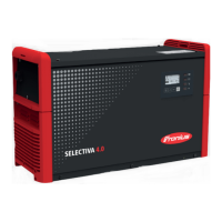
Fit the PFC inductor connections to the
primary rectifier (2) in the correct se-
quence:
- Primary rectifier
- PFC cable
- Varistor
- One 5x10 TX25 tapping screw [3
Nm]
Close the front panel and the housing
cover (see the "Closing the device"
section)
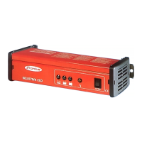
Replacing the op-
tional PC board
Removing the optional PC board:
Remove the front panel and the
housing cover (see the "Opening the
device" section)
Undo all plug connections (1)
Undo partitions and end connectors (2)
Undo the four 4x9 TX20 tapping
screws (3)
Undo the four fuse holders (3)
Remove the optional PC board
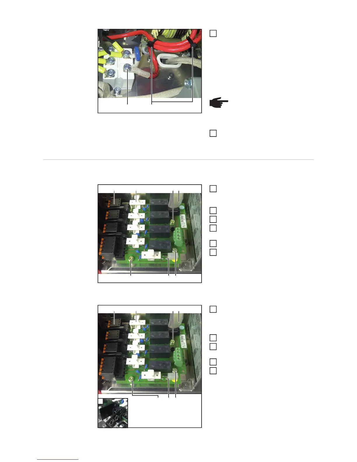
Installing the optional PC board:
Insert the new optional PC board and
fit it with four 4x9 TX20 tapping screws
(3)
[2 Nm]
Fit all plug connections (1)
Insert the partitions (2) onto the optio-
nal PC board
Fit the four fuse holders (3)
Fit the front panel and the housing co-
ver (see the "Closing the device" secti-
on)
(2) (4)
NOTE! The PFC inductor connec-
tions must be bound with type 200
cable ties (4)
3
4
(2)
(4)
(3) (3)
(3)(1)
(1)
1
2
3
4
5
6
(2)
(4)
(3)
(3)(1)
(1)(3)
2
1
2
3
4
5
 Loading...