117
EN
Replacing the 16
kW primary pow-
er module
Removing the primary power module:
Remove the front panel and the AC
connecting plate (see the "Opening the
device" section)
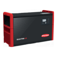
Disconnect the primary power module
supply lines (L1, L2, L3, N) from the
mains terminal
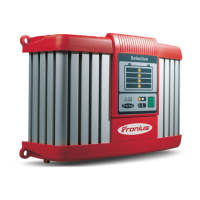
Undo the nine 5x10 TX25 tapping
screws (1, 2, 3)
Undo the ribbon cable connection (4)
to the P-control
Remove the axial fan (5) from the
strain-relief device and disconnect it
from the primary power module
When removing the primary power mo-
dule, make sure that the transformer/
inductor connections (2, 3) are threa-
ded out
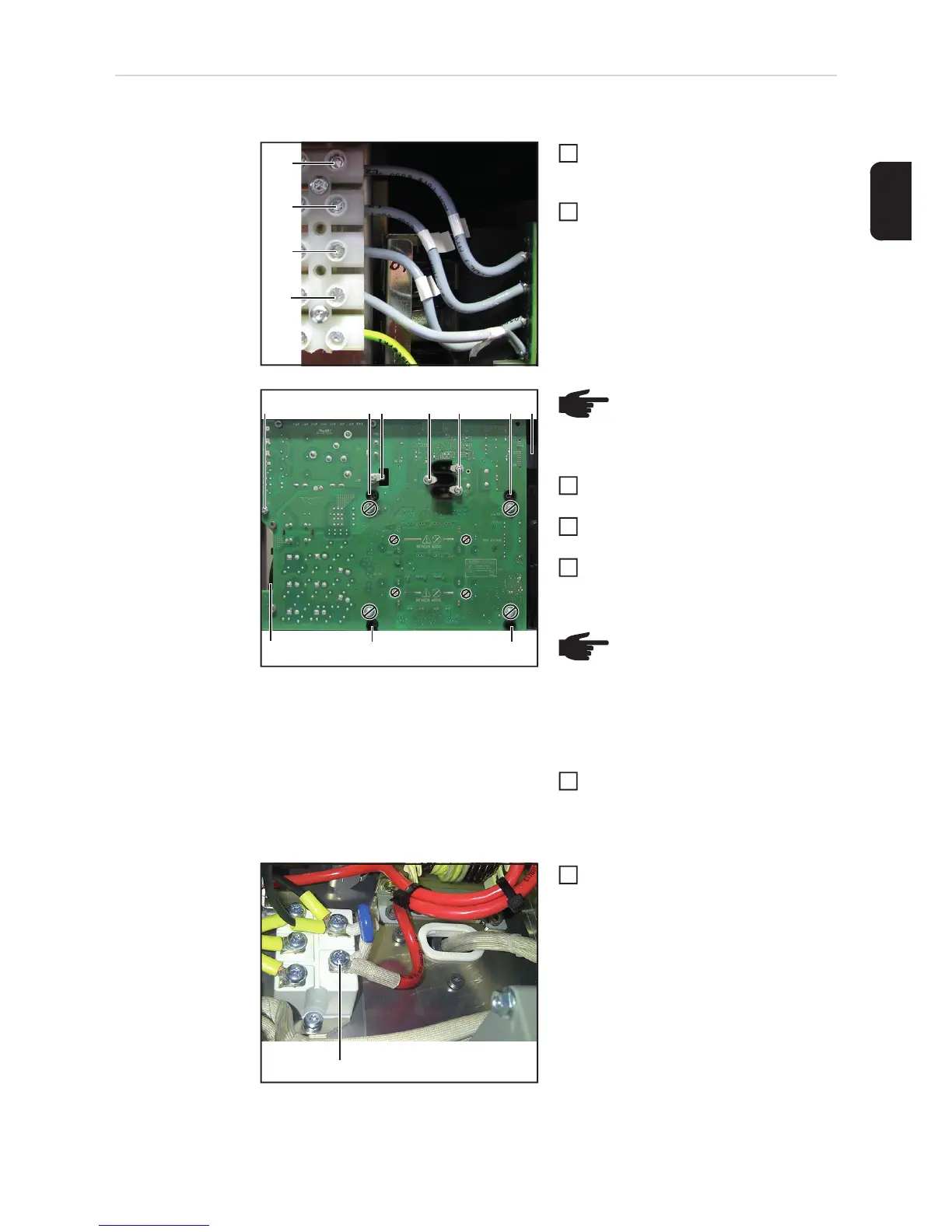
Undo the 5x10 TX25 tapping screw (6)
on the PFC inductor connection to the
primary rectifier on the inside of the pri-
mary power module
(L1)
(L2)
(L3)
(N)
1
2
(5)
(4)(1)
(1)(1)
(1)(1) (2) (3) (3)
NOTE! The connections marked
by a circle with a line through it
must not be disconnected
NOTE! As an option, the assem-
bly aid can be mounted onto the
bottom of the device by means of
two 5x12 TX25 screws, in order to
facilitate fitting and disassembling
the primary power module
3
4
5
6
(6)
7
 Loading...