119
EN
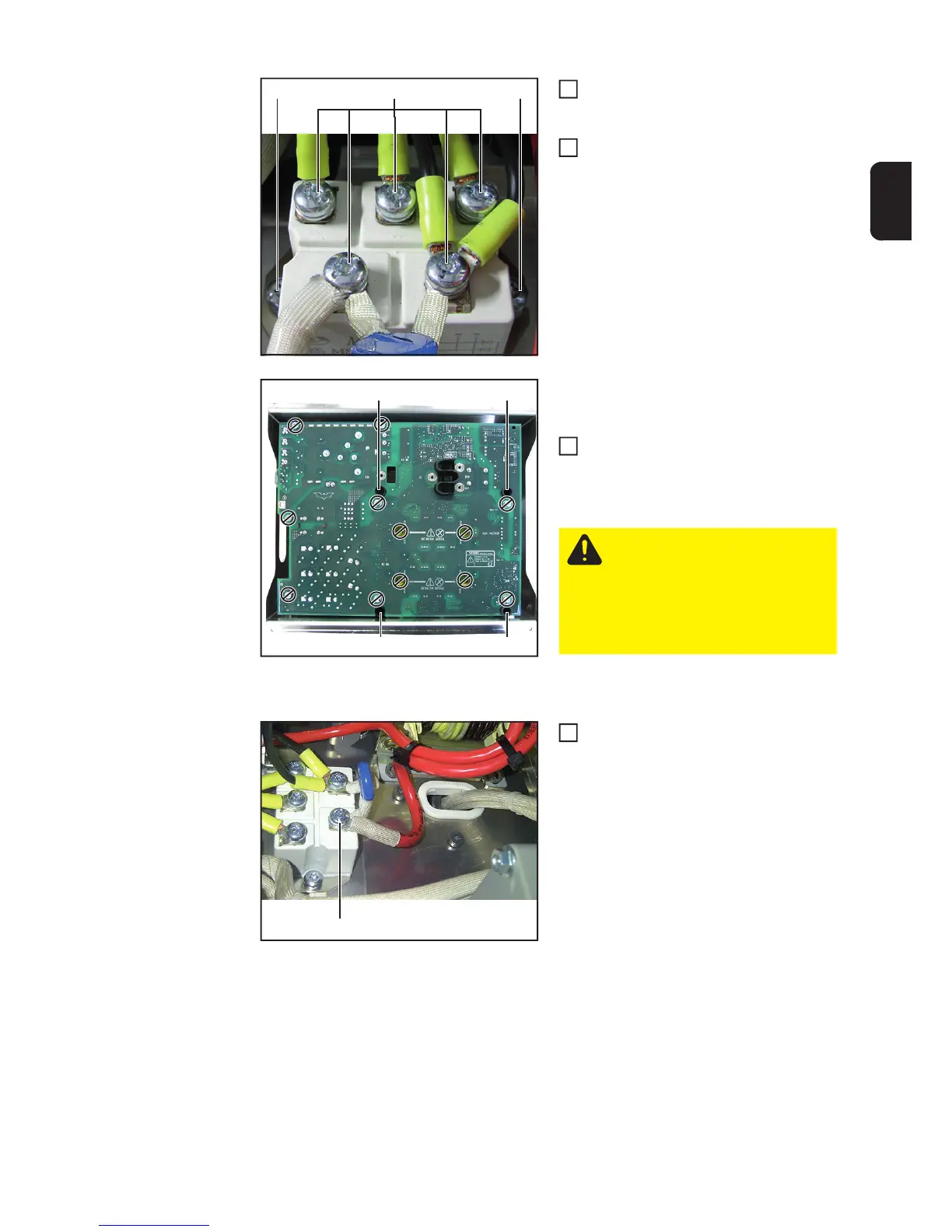
Place the primary rectifier in position
and fit it with two 5x16 TX25 screws (8)
[3 Nm]
Connect the five 5x10 TX25 screws (7)
on the cable connections to the pri-
mary rectifier
[3 Nm]
Removing the primary power module
from the replacement packaging:
Undo the four 5x10 TX25 tapping
screws (9) and remove from the packa-
ging frame
Installing the primary power module:
Place the new primary power module
in position
- Fit the PFC inductor connection
(6) to the primary rectifier in the
correct sequence:
Primary rectifier
PFC cable
Varistor
One 5x10 TX25 tapping
screw [3 Nm]
(8) (7) (8)
5
6
(9)
(9)
(9) (9)
CAUTION! The faulty primary
power module must be screwed
into the replacement packaging
and returned to Fronius! No guar-
antee or warranty claims can be
made if the item is not returned
properly!
1
(6)
1
 Loading...