120
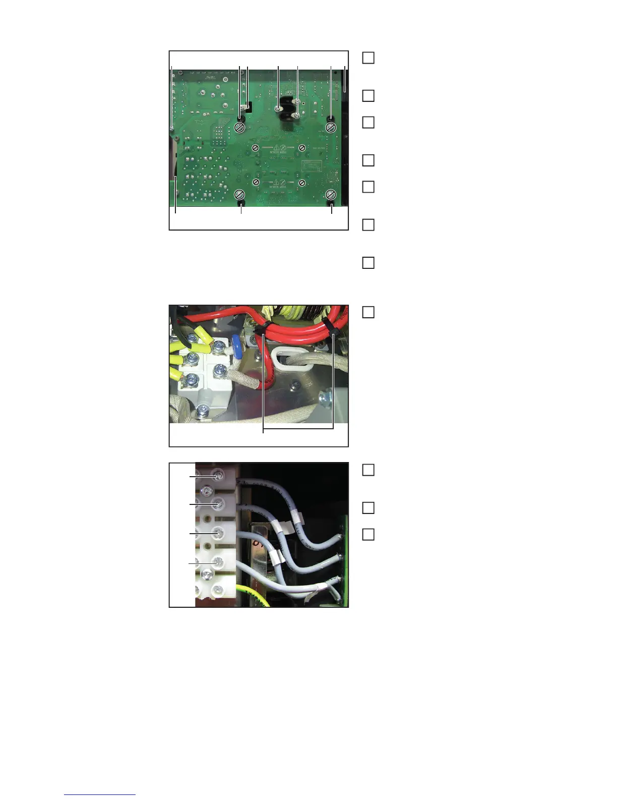
Correctly thread the transformer
connection (3) and the inductor
connection (2)
Now fully insert the primary power mo-
dule and position it correctly
Insert the axial fan (5) in the strain-re-
lief device provided and connect it to
the primary power module
Establish the ribbon cable connection
(4) to the P-control
Fit the primary power module with five
5x10 TX25 tapping screws (1)
[3 Nm]
Fit the transformer connection with
three 5x10 TX25 tapping screws (3)
[4.5 Nm]
Fit the inductor connection with one
5x10 TX25 tapping screw (2)
[4.5 Nm]
Make sure the inductor leads are laid
parallel and bind them with two type
200 cable ties (10)
Fit the primary power module supply
(L1, L2, L3, N) to the mains terminal
[1.5 Nm]
In case the assembly aid has been
mounted, remove it
Fit the front panel and the AC connec-
ting plate (see the "Closing the device"
section)
(5)
(4)(1)
(1)(1)
(1)(1) (2) (3) (3)
2
3
4
5
6
7
8
(10)
9
(L1)
(L2)
(L3)
(N)
10
11
12
 Loading...