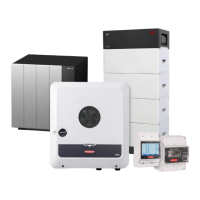
Device configuration
Components Select "Add component+" to add all available components to the system.
PV generator
Activate the MPP tracker and enter the connected PV power in the associated field. For
combined solar module strings, "PV 1 + PV 2 connected in parallel" must be activated.
Battery
If the SoC mode is set to "Automatic", the values "Minimum SoC" and "Maximum SoC"
are preset according to the technical specifications of the battery manufacturer.
If the SoC mode is set to "Manual", the values "Minimum SoC" and "Maximum SoC" may
be changed after consultation with the battery manufacturer within the scope of their
technical specifications. In the event of a power outage, the set values are not taken into
account.
Using the "Allow battery charging from additional producers in home network" setting,
charging of the battery from other external producers is enabled/disabled.
Using the "Allow battery charging from public grid" setting, charging of the battery from
the public grid is enabled/disabled.
The normative or feed-in tariff rules must be taken into account with this setting. The set-
ting does not affect the charging of the battery by other producers within the home. It
merely relates to the process of drawing charging energy from the public grid. Regard-
less of this setting, any charging from the public grid that is required for service reasons
(e.g. necessary re-charging to protect against deep discharge) is still performed.
IMPORTANT!
Fronius accepts no liability for damage to third-party batteries.
Primary meter
To ensure smooth operation in conjunction with other energy producers and in Full
Backup backup power mode, it is important to install the Fronius Smart Meter at the
feed-in point. The inverter and other producers must be connected to the public grid via
the Fronius Smart Meter.
This setting also affects the behaviour of the inverter at night. If the function is deactiv-
ated, the inverter switches to Standby mode as soon as there is no more PV power avail-
able, provided that no energy management command is sent to the battery (e.g. minim-
um state of charge reached). The message "Power low" is displayed. The inverter re-
starts as soon as an energy management command is sent or sufficient PV power is
available.
If the function is activated, the inverter remains permanently connected to the grid so that
energy can be drawn from other producers at any time.
After connecting the meter, the position must be configured. A different Modbus address
needs to be set for each Smart Meter.
The Watt value on the generator meter is the sum of all generator meters. The Watt
value on the consumption meter is the value of all secondary meters.
Ohmpilot
All Ohmpilots available in the system are displayed. Select the desired Ohmpilot and add
it to the system via "Add".
Functions and
I/Os
Backup power
"Off", "PV Point" or "Full Backup" can be selected for backup power mode.
Full Backup can only be activated once the required I/O assignments have been con-
figured for backup power. In addition, a meter must be mounted and configured at the
96
 Loading...


