iii
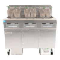
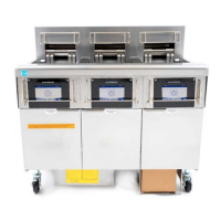
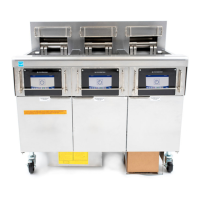
OCF30
™
SERIES ELECTRIC FRYERS
TABLE OF CONTENTS
CAUTIONARY STATEMENTS .............................................................................................................................. i
ELECTRICAL POWER SPECIFICATIONS ........................................................................................................ ii
CHAPTER 1: Service Procedures
1.1 General ................................................................................................................................................... 1-1
1.2 Replacing a Controller ........................................................................................................................... 1-1
1.3 Replacing Component Box Components ............................................................................................... 1-1
1.4 Replacing a High-Limit Thermostat ...................................................................................................... 1-3
1.5 Replacing a Temperature Probe ............................................................................................................. 1-3
1.6 Replacing a Heating Element ................................................................................................................. 1-5
1.7 Replacing Contactor Box Components .................................................................................................. 1-6
1.8 Replacing a Frypot ................................................................................................................................. 1-7
1.9 Built-In Filtration System Service Procedures ....................................................................................... 1-9
1.9.1 Filtration System Problem Resolution .................................................................................... 1-9
1.9.2 Replacing the Filter Motor, Filter Pump and Related Components ...................................... 1-10
1.9.3 Replacing the Filter Transformer or Filter Relay ................................................................. 1-12
1.10 Basket Lift Service Procedures ............................................................................................................ 1-12
1.11 ATO (Automatic Top-Off) Service Procedures ................................................................................... 1-14
1.11.1 ATO (Automatic Top-Off) Troubleshooting) ....................................................................... 1-15
1.11.2 Testing ATO RTD Probes ..................................................................................................... 1-16
1.11.3 ATO (Automatic Top-Off) Board Pin Positions and Harnesses ........................................... 1-17
1.11.4 Replacing the ATO board, ATO Pump Relay or Transformer ............................................. 1-18
1.11.5 Replacing the ATO Pump ..................................................................................................... 1-18
1.11.6 Replacing the ATO Solenoids ............................................................................................... 1-18
1.11.7 Control Power Reset ............................................................................................................. 1-19
1.12 3000 Controller Service Procedures .................................................................................................... 1-19
1.12.1 3000 Controller Troubleshooting .......................................................................................... 1-19
1.12.2 3000 Controller Useful Codes ............................................................................................... 1-22
1.12.3 Service Required Errors ........................................................................................................ 1-22
1.12.4 Error Log Codes .................................................................................................................... 1-23
1.12.5 3000 Menu Summary Tree ................................................................................................... 1-24
1.12.6 3000 Controller Pin Positions and Harnesses ....................................................................... 1-25
1.13 Loading and Updating Software .......................................................................................................... 1-26
1.14 Interface Board Diagnostic Chart ........................................................................................................ 1-27
1.15 Probe Resistance Chart ........................................................................................................................ 1-28
1.16 Wiring Diagrams .................................................................................................................................. 1-28
1.16.1 Series Data Network Flowchart .......................................................................................... 1-28
CHAPTER 2: Parts List
2.1 Accessories ............................................................................................................................................ 2-1
2.2 Basket Lift Assembly and Associated Parts .......................................................................................... 2-2
2.3 Doors, Sides, Tilt Housings, Top Caps and Casters .............................................................................. 2-4
2.4 Drain System Components .................................................................................................................... 2-5
2.4.1 Drain Tube Sections and Associated Parts ........................................................................... 2-5
2.4.2 Drain Valve Assembly .......................................................................................................... 2-7
2.5 Electronics and Wiring Components ..................................................................................................... 2-8
2.5.1 Component Boxes ................................................................................................................. 2-8
2.5.2 Contactor Boxes .................................................................................................................. 2-10
2.5.3 Fuse Boxes .......................................................................................................................... 2-11
2.5.4 Terminal Blocks .................................................................................................................. 2-12
2.5.5 Heating Element Assemblies and Hardware ....................................................................... 2-13
2.5.6 Element Tube Assemblies................................................................................................... 2-15