2-10
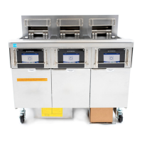
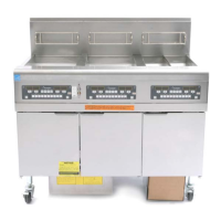
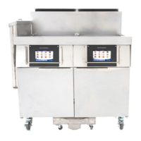
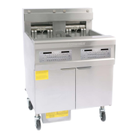
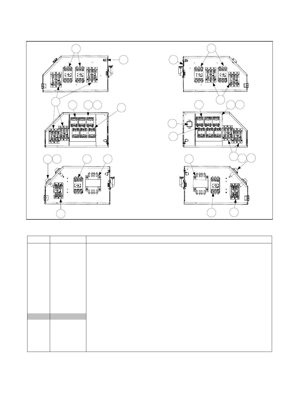
2.5.2 Contactor Boxes
120/440/480v
LEFT AND RIGHT
STANDARD AND
MECHANICAL
CONFIGURATIONS
SOLID STATE RELAY
LEFT AND RIGHT
CONFIGURATIONS
14/17kW
LEFT AND RIGHT
MECHANICAL
CONFIGURATIONS
9
10
13
11
12
7
7
5
8
13 11 12
10
9
7
9 3
7
2
1 3
9
7
2
1
4
NOTES: The configurations illustrated show all possible components, but a particular
configuration may not have all the components shown.
ITEM PART # COMPONENT
1 807-2278 Fuse, 20 Amp
2 807-0922 Holder, Bus Fuse
3 807-0064 Transformer, 480V/120V 150VA
4 106-6204 Filter Assembly, EPRI (Used on some CE WYE configurations)
5 810-2554 Plug, Cord Cutout 1.125 Button
6 807-1947 Plug, .875 Diameter Dome
7 810-1202 Contactor, 24V 40 Amp Mechanical (Latch)
8 807-0070 Terminal, Ground Lug
9 807-2284 Contactor, 24V 50 Amp Mechanical (only in 14kW & 17kW units) (Heat)
10 807-0037 Terminal, ¼-inch Push-on
11** 806-8673 Heatsink Assembly, FV Solid State Relay (See components below)
Components of Items 12 and 13
12 826-1562 Kit Relay, Solid State 40 Amp 280V with Heatsink
13 807-2749 Heatsink, Solid State
* 221-0482 Cover, Left Contactor Box
* 222-0482 Cover, Right Contactor Box
* 807-0012 Relay, Tilt Switch 18 Amp 1/3 HP 24 V Coil
* Not illustrated. ** Full Vat has three relays 826-1562, Dual-Vat has six relays.