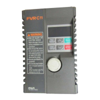
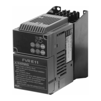
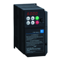
FVR-C11S-EN
2-8 2 Installation and Connection
2
*Note the followin
when wirin
:
1) Sur
e absorber connection
When the excitin
coil of the ma
netic con-
tactor or rela
in the control circuit or inverter
peripheral circuit is opened or closed, a sur
e
volta
e (noise) is
enerated with a sudden
current chan
e. Due to this sur
e volta
e,
the inverter control circuit or peripheral equip-
ment ma
malfunction. If so, directl
connect
a sur
e absorber to both ends of the coil.
(See Fi
ure 2-3-4).
Fi
ure 2-3-4 Sur
e absorber connection dia
ram
2) Control circuit wirin
1. Wires connected to control circuit termi-
nals must be 0.5mm
2
shielded wire or
twisted vin
l wire. Remove the sheath as
shown in Fi
ure 2-3-5 and then connect it.
Fi
ure 2-3-5 End treatment
2. Keep the wirin
of the main circuit, exter-
nal rela
sequence circuit and control cir-
cuit as far awa
from each other as
possible. If the
must be adjacent, cross
them at ri
ht an
les.
3. Use a twisted-pair shielded wire for lon
wirin
distances.
3) Shieldin
sheath connection
Connect one end of the shieldin
sheath of a
shielded or twisted-pair shielded wire to the
round terminal as shown in Fi
ure 2-3-6. Do
not connect the other end.
Fi
ure 2-3-6 Connection of sheath of shielded wire
+
-
Ry
D
MC
SK
SK: Sur
e absorber D: Diode
AC rela
DC rela
6 ±1mm
P24/CM
13
12
11
FWD
Contact
Shield
Shield
Frequenc
settin
POT
To
round terminal
To
round terminal
CAUTION
Noise is
enerated from the inverter,
motor, and wirin
. Take care that this
noise does not cause malfunctions in
peripheral sensors and equipment.
Otherwise accidents could occur.

 Loading...


