Machine Components
65
Product Overview
2
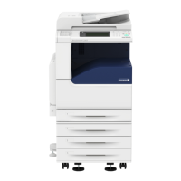
6 Machine front door Open this door to clear paper jams or replace consumables.
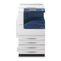
7 Tray 1, 2, 3, 4 Load paper here.
8 Bottom left door Open this door to clear paper jams.
If Tray 6 (HCF2 (2000 sheets)) is installed in the machine, move Tray 6
(HCF2 (2000 sheets)) to the left first.
9 Locking casters Casters which prevents the machine from moving. Lock these casters after
moving the machine to its installation site.
10 Tray 6 (optional) Load paper here.
11 Tray 6 top cover Move Tray 6 (HCF2 (2000 sheets)) to the left and then open this top cover
to clear paper jams.
12 Tray 5 (Bypass) Used for loading non-standard paper (thick-stock paper, and other special
media) that cannot be loaded in Trays 1 to 4, and 6.
13 Tray 5 (Bypass) top cover Open the top cover to clear paper jams.
14 Gigabit Ethernet (optional) Connected to a network cable.
15 10BASE-T/100BASE-TX
connector
Connected to a network cable. This connector is not available when the
Gigabit Ethernet (optional) is installed.
16 USB 2.0 interface
connector
Connected to a USB cable.
17 Stylus pen Used for touching the touch screen on the control panel to configure
settings.
Note • You can directly touch the touch screen not only with the stylus pen but
also with a finger.
18 Stylus pen holder Stores the stylus pen.
19 Control panel (Large Size UI
Kit)
Consists of operation buttons, LED indicators, and a touch screen.
For more information, refer to "Large Size UI Kit" (P.80).
No. Component Function
 Loading...