12-14
12.2 Laser Optical Unit
• Do not bend the coaxial cables between the color
tube and the connector.
• When the laser optical unit has been replaced,
perform the following adjustments.
1) Menu 0522 “G Laser (SHG) Optimal
Temperature Setup”(See Subsection 5.6.2)
2) Menu 0547 "Main Scan/Laser Beam Sync.
Rough Adjustment"(See Subsection 5.6.15)
3) Menu 0548 "Laser Beam Sync. Fine Adjustment
Print"(See Subsection 5.6.16)
4) Menu 0554 "Image Position Initial Setting"
(See Subsection 5.6.22)
Removal
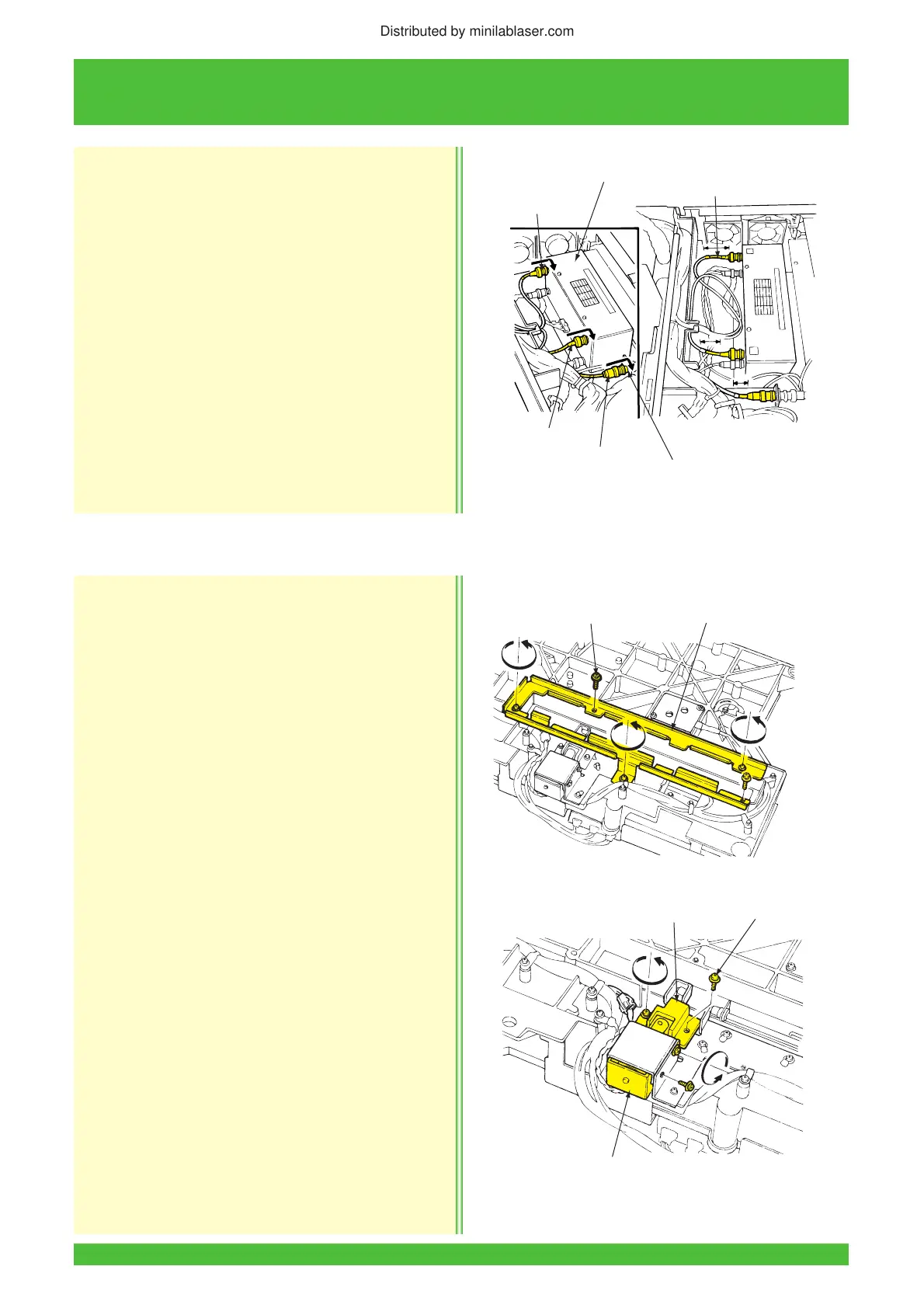
1. Remove the laser optical unit (See Subsection 12.2.3).
2. Remove the five screws and then the shutter
section lower bracket.
3. Disconnect the solenoid connector and remove
the four screws then the guide and the solenoid.
Installation
Installation is essentially in the reverse order of removal.
LII322
G Coaxial Cable
AOM Driver
Color Tube
Relay Connector
R Coaxial Cable
B Coaxial Cable
12.2.4 Shutter Solenoid (S673) Replacement
LII462
Screws (5)
Shutter Section Lower Bracket
LII463
Screws (4)
Guide
Solenoid (S673)
Distributed by minilablaser.com




 To Next Page