ETERNUS DX900 S5
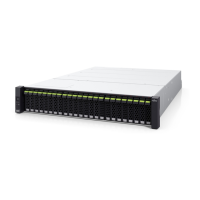
The ETERNUS DX900 S5 controller enclosure contains an operation panel, battery units, PCIe Flash Modules
(PFMs), and drives installed in the front and controllers (CMs), host interfaces (CAs), and power supply units in
the rear.
● Front View
Figure 152 Front View of a Controller Enclosure (for ETERNUS DX900 S5, with a Front Cover)
1 Operation panel
An operation panel has LEDs, a Power switch, and setting change switches.
2 Front cover
Figure 153 Front View of a Controller Enclosure (for ETERNUS DX900 S5, without a Front Cover)
1 2
3 3
BBU#1BBU#0
Slot#0
Slot#1
Slot#2
Slot#3
Slot#4
Slot#5
Slot#6
Slot#7
Slot#8
Slot#9
Slot#10
Slot#11
Slot#12
Slot#13
Slot#14
Slot#15
Slot#16
Slot#17
Slot#18
Slot#19
Slot#20
Slot#21
Slot#22
Slot#23
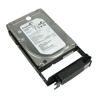
1 2.5" drive
(Refer to "■ Drives" (page 265
).)
2 2.5" drive / PCIe Flash Module
(Refer to "■ Drives" (page 265) and "■ PCIe Flash Module (PFM) (ETERNUS DX500 S5/DX600 S5/DX900
S5)" (page 264))
3 Battery (BBU#0, BBU#1)
(Refer to "■ Battery (ETERNUS DX500 S5/DX600 S5/DX900 S5)" (page 264).)
6. Hardware Configurations
Controller Enclosure
255 Design Guide
 Loading...