List of Figures
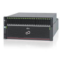
Figure 1.1 Front View of a Controller Enclosure (with a Front Cover).........................................................................12
Figure 1.2 Front View of a Controller Enclosure (without a Front Cover)....................................................................13
Figure 1.3 Rear View of a Controller Enclosure (ETERNUS DX500 S3) ........................................................................14
Figure 1.4 Rear View of a Controller Enclosure (ETERNUS DX600 S3) ........................................................................14
Figure 1.5 Operation Panel (Controller Enclosure) ....................................................................................................15
Figure 1.6 PFM..........................................................................................................................................................16
Figure 1.7 Battery .....................................................................................................................................................17
Figure 1.8 Controller (ETERNUS DX500 S3)................................................................................................................18
Figure 1.9 Controller (ETERNUS DX600 S3)................................................................................................................19
Figure 1.10 Controller LEDs.........................................................................................................................................20
Figure 1.11 Host Interface (4port) ..............................................................................................................................21
Figure 1.12 Host Interface (2port) ..............................................................................................................................21
Figure 1.13 Power Supply Unit (Controller Enclosure).................................................................................................22
Figure 1.14 Front View of a 2.5" Type Drive Enclosure.................................................................................................23
Figure 1.15 Front View of a 3.5" Type Drive Enclosure.................................................................................................23
Figure 1.16 Rear View of a 2.5" Type / 3.5" Type Drive Enclosure.................................................................................24
Figure 1.17 Operation Panel (2.5"/3.5" Type Drive Enclosure).....................................................................................24
Figure 1.18 2.5" Drives................................................................................................................................................25
Figure 1.19 Drive Slot Numbers (2.5" Type Drive Enclosure) .......................................................................................25
Figure 1.20 3.5" Drives................................................................................................................................................26
Figure 1.21 Drive Slot Numbers (3.5" Type Drive Enclosure) .......................................................................................26
Figure 1.22 I/O Module (2.5" / 3.5" Type Drive Enclosure) ...........................................................................................27
Figure 1.23 Power Supply Unit (2.5"/3.5" Type Drive Enclosure)..................................................................................28
Figure 1.24 High-density Drive Enclosure ...................................................................................................................29
Figure 1.25 Rear View of a High-density Drive Enclosure ............................................................................................29
Figure 1.26 Operation Panel (High-density Drive Enclosure) ......................................................................................30
Figure 1.27 Disk Activity Panel (DAP)..........................................................................................................................31
Figure 1.28 Drives for High-density Drive Enclosures ..................................................................................................32
Figure 1.29 Drive Slot Numbers for High-density Drive Enclosures..............................................................................32
Figure 1.30 I/O Module (High-density Drive Enclosure) ..............................................................................................33
Figure 1.31 Fan Expander Module ..............................................................................................................................34
Figure 1.32 Power Supply Unit (High-density Drive Enclosure) ...................................................................................35
Figure 1.33 Front View of a 19-inch Rack ....................................................................................................................36
Figure 1.34 Rear View of a 19-inch Rack .....................................................................................................................37
Figure 1.35 Power distribution unit for DX500 S3/DX600 S3 (AC200-240V, 1U 4Outlets) ............................................38
Figure 1.36 Power distribution unit for DX500 S3/DX600 S3 (AC200-240V, 2U, 12Outlets) .........................................39
Figure 1.37 Power distribution unit for DX500 S3/DX600 S3 (AC200-240V, 2U, 16Outlets) .........................................39
Figure 2.1 ON Position (Marked "|") of the Main Line Switches on a 1U Power Distribution Unit ..............................43
Figure 2.2 ON Position (Marked "|") of the Main Line Switches on a 2U Power Distribution Unit ..............................43
Figure 2.3 OFF Position (Marked "¡") of the Main Line Switches on a 1U Power Distribution Unit ...........................44
Figure 2.4 OFF Position (Marked "¡") of the Main Line Switches on a 2U Power Distribution Unit ...........................44
Figure 2.5 ON Position (Marked "|") of the PSU Switch on a Power Supply Unit ........................................................45
Figure 2.6 OFF Position (Marked "¡") of the PSU Switch of a Power Supply Unit ......................................................46
Figure 3.1 ETERNUS Web GUI Screen.........................................................................................................................50
Figure 3.2 Event Notification ....................................................................................................................................53
Figure 3.3 Audit Log..................................................................................................................................................53
10
FUJITSU Storage ETERNUS DX500 S3/DX600 S3 Disk storage system Operation Guide (Basic)
Copyright 2014 FUJITSU LIMITED
P3AM-7742-04ENZ0

 Loading...