Fulton ProtoNode Start-up Guide
Page 12 of 47
4.1.2 Interfacing ProtoNode to Honeywell SOLA Controller
There are two profiles available when interfacing with the Honeywell SOLA controller. Hydronic Sola is
utilized for each boiler when the all points are needed for each boiler and Hydronic Sola Master is
available for when pulling information from just the Master boiler is sufficient.
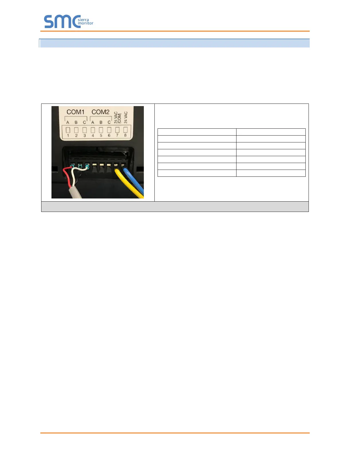
Refer to the boiler Installation and Operation Manual and the electrical drawing for specific wiring
requirements. The 24VAC transformer being used to power the SOLA display on Fulton boilers can be
used to also power the ProtoNode. Do not wire the 24VAC ground terminal on the ProtoNode.
SOLA Settings at the Boiler:
• From the home screen select Setup on the lower left right corner then select Display Setup.
• Select the COM 2 tab and check the option for Enable COM2 Port. From there, verify that the
baud rate is set to 19200.
• Select the Gateway tab and check both the Enable Modbus Gateway and Gateway on COM2
Port options.
• Press Save on the bottom right corner.
• To set the Modbus address, select Configure from the boiler menu and then select System
Identification and Access from the top of the list.
• Scroll down to MB2 Modbus Address; this should be set to the boilers’ number (boiler 1 is set to
address 1). If login is required, use password sola.
• Power may need to be cycled to the boiler panel before communication will start.
NOTE: If multiple boilers are connected to the ProtoNode and the Hydronic Sola profile is selected
for each boiler, the above procedure will need to be done at each boiler. The Modbus address will
increase with each additional boiler (Boiler 2 MB2 address set to 2, Boiler 3 MB2 address set to 3
and so on). This will also require the Modbus COM2 connection at the displays to be daisy
chained between the boilers.
 Loading...