Fulton ProtoNode Start-up Guide
Page 36 of 47
Appendix A.4 LED Diagnostics for Communications Between ProtoNode and Devices
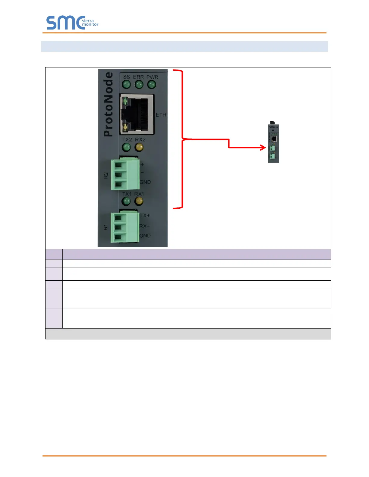
See the diagram below for ProtoNode FPC-N54 LED Locations.
The SS LED will flash once a second to indicate that the bridge is in operation.
The SYS ERR LED will go on solid indicating there is a system error. If this occurs, immediately report
the related “system error” shown in the error screen of the FS-GUI interface to support for evaluation.
This is the power light and should always show steady green when the unit is powered.
The RX LED will flash when a message is received on the serial port on the 3-pin connector.
If the serial port is not used, this LED is non-operational. RX1 applies to the R1 connection while
RX2 applies to the R2 connection.
The TX LED will flash when a message is sent on the serial port on the 3-pin connector.
If the serial port is not used, this LED is non-operational. TX1 applies to the R1 connection while
TX2 applies to the R2 connection.
Figure 28: Diagnostic LEDs
 Loading...