Do you have a question about the FULTON ProtoNode FPC-N54 and is the answer not in the manual?
Record unit identification data for technical support purposes.
Ensure matching COM settings between the ProtoNode and connected devices.
Connect the ProtoNode's R1 port to the RS-485 network for device communication.
Connect the power supply to the ProtoNode's power port.
Establish an Ethernet connection between the PC and the ProtoNode.
Access the Web Configurator to configure attached devices and load profiles.
Explanation of the BTL mark as a symbol of high-quality BACnet products.
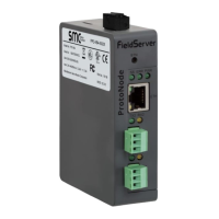
Description of the ProtoNode as a building automation multi-protocol gateway.
Record the unique part number of the ProtoNode for technical support.
Details on the ProtoNode's supported point count and registers per device.
Settings for configuring Modbus device communications, including COM settings.
Ensuring matching baud rate, data bits, stop bits, and parity for serial devices.
Assigning unique Node-IDs (1-255) to devices connected to the ProtoNode.
Connecting RS-485 devices to the ProtoNode's R1 port using standard grounding.
Profile selection and wiring for interfacing ProtoNode with ModSync SE.
Steps for connecting and configuring the ProtoNode with Honeywell SOLA controllers.
Configuration for interfacing ProtoNode with Endura+ (PURE) boilers.
Settings and wiring for connecting ProtoNode to Siemens LMV3x controllers.
Configuration steps for interfacing ProtoNode with Siemens LMV5x controllers.
Configuration for interfacing ProtoNode with Siemens LMV3x and Yokogawa controllers.
Configuration for interfacing ProtoNode with Siemens LMV3x and RWF55 controllers.
Establishing an Ethernet connection using a Cat-5 cable.
Setting static IP address and subnet for the PC for network communication.
Steps to access the ProtoNode's web interface for configuration.
Navigating settings and configuration tabs within the web interface.
Procedure for adding device profiles and assigning Node-IDs in the web configurator.
Using FS-GUI to set IP address, Netmask, and Gateway for the ProtoNode.
Steps to locate the ProtoNode's IP address using FieldServer Toolbox.
How to view connection status and error messages in the web interface or toolbox.
Steps to diagnose communication issues by checking wiring, COM settings, and device listing.
Interpreting ProtoNode LED indicators for communication status and system errors.
Methods for capturing diagnostic data using FieldServer Toolbox or FS-GUI.
Step-by-step guide to taking diagnostic logs using the FieldServer Toolbox application.
Procedure for completing diagnostic captures and sending log files.
Capturing network traffic via FS-GUI for troubleshooting Ethernet and Wi-Fi connections.
Instructions for loading new firmware versions onto the ProtoNode.
Enabling and managing user and admin passwords for ProtoNode access.
Guidance on resetting the FieldServer to its factory default state.
List of internet browsers not compatible with the ProtoNode interface.
Information on mounting the ProtoNode using its DIN rail bracket.
Technical specifications including electrical, power, approvals, dimensions, and operating conditions.
Instructions for UL compliance, including power supply and cable requirements.
| Brand | FULTON |
|---|---|
| Model | ProtoNode FPC-N54 |
| Category | Control Unit |
| Language | English |