VMP-IOMM-2018-2
Fulton Ltd
Page 11
INSTALLATION - 2
2.4.5 STEAM PRESSURE GAUGE
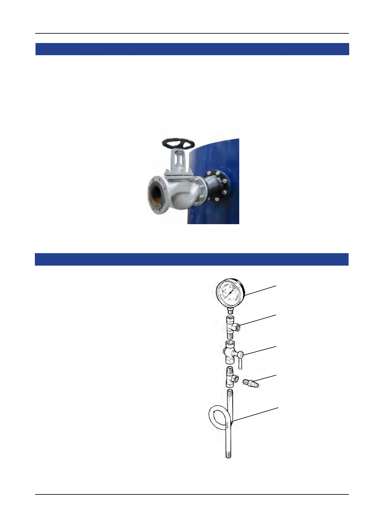
The steam pressure gauge assembly
should be assembled in accordance
with Figure. 8 using a suitable sealant
on all joints.
The gauge should be facing front
towards the electrical control box and/
or the operator of the boiler.
Screw the assembly into the top of
the water level gauge (sight glass)
and connect the copper tube from
the pressure controller located on the
side of the control box to the nipple
provided on the assembly.
Test Point
Steam Pressure Gauge
Steam Cock
Syphon
Plugged
Figure. 8 - Steam Pressure Gauge
Distribution pipework should be run from the main steam valve on the boiler to the steam delivery
point(s). Care should be taken to ensure that adequate condensate drainage and expansion
facilities are provided within the pipework run(s).
To prevent excessive loads being imposed on the main steam isolating valve, the pipework
shouldbesecuredneartheboiler,ensuringadequateexibilityexistsinthepipeworkbetweenthe
steam valve and the securing point, to minimise any loads imposed on the valve.
2.4.4 MAIN STEAM VALVE
Figure. 7 - Main Steam Valve