VMP-IOMM-2018-2
Fulton Ltd
Page 59
TROUBLESHOOTING - 6
SECTION 6 -
TROUBLESHOOTING
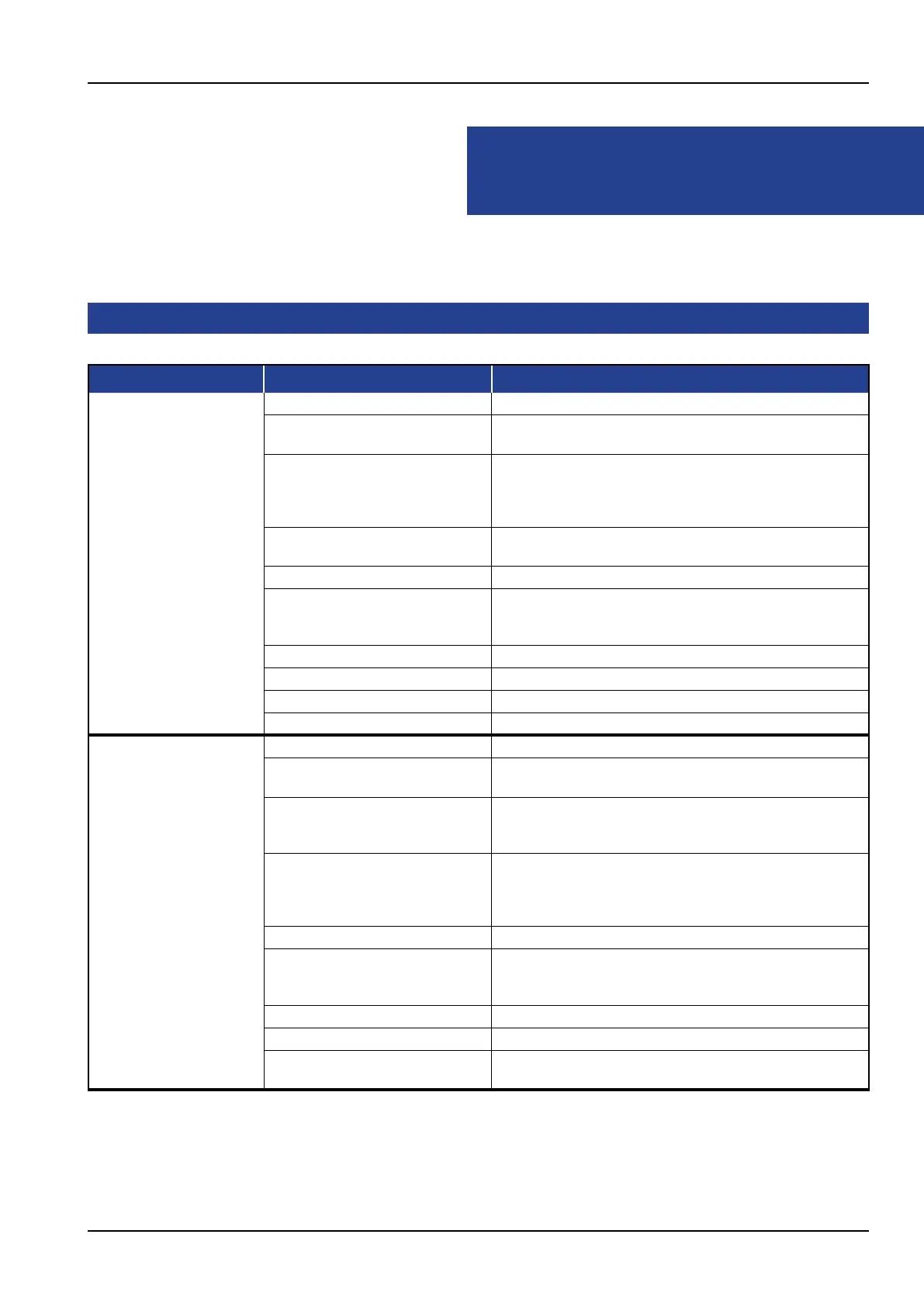
6.1 TROUBLESHOOTING GAS BOILER
Problem Cause Remedy
1. Ignition Failure 1. Gas supply Check for gas pressure and intermittent supply problems.
2. Power Supply Check fuse or circuit breaker.
Reset or Replace as required.
3. Ignition Electrodes Check for cracks in porcelain,if found replace the
electrode. Check electrodes for carbon build-up.
Clean as required.
Check settings, adjust if required.
4. Transformer Check voltage between transformer leads at terminal block
to be sure transformer is live.
5. UV Detector Check for ignition interference.
6. Burner Control Check voltage between ignition terminal and neutral, this
check must be made before the control locks out. If no
power, replace the control.
7. Air Settings Check main air adjustment and secondary air adjustment.
8. Faulty Air Switch Check for faulty air switch.
9. Gas Valve Checkltersinthevalveblock.Cleanasrequired.
10. Loose wire connections Check connections to all components.
2. Flame Failure During
Start-up
1. Gas supply Check for gas pressure and intermittent supply problems.
2. Power Supply Check fuse or circuit breaker.
Reset or Replace as required.
3. Air Settings Checkairadjustment.Airmaybeblowingameawayfrom
theUVdetector.Openprimaryairuntilrebrushesthe
furnace wall.
4. Ignition Electrodes Check for cracks in porcelain,if found replace the
electrode. Check electrodes for carbon build-up.
Clean as required.
Check settings, adjust if required.
5. UV Detector Check the detector is located correctly and clean.
6. Burner Control Check voltage between ignition terminal and neutral, this
check must be made before the control locks out. If no
power, replace the control.
7. Loose wire at fuel valve circuit. Tighten wiring connections.
8. Contact open on Air Switch Adjust to the correct setting.
9. UV Detector wiring reversed at
control box.
Change to the correct terminals.
CONTINUED ON NEXT PAGE