VMP-IOMM-2018-2
Fulton Ltd
Page 75
TROUBLESHOOTING - 6
242/254
Building Technologies Division Basic documentation LMV26... CC1P7547en
30 Error code list 20.04.2016
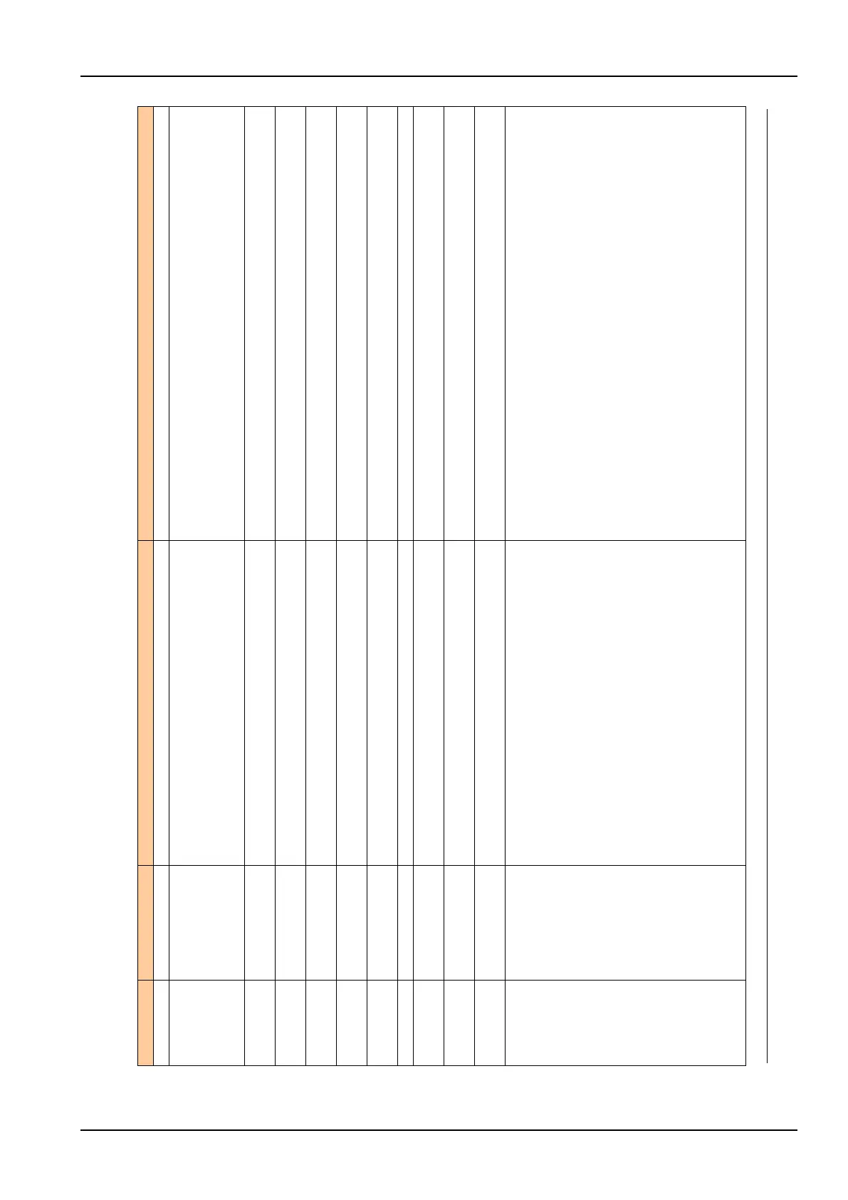
Error code Diagnostic code Meaning for the LMV26... system Remedy
21 Safety loop / burner flange open
Safety loop or burner flange is open repeat standardization with safety loop closed
22 Air actuator not referenced
Air actuator has not been referenced or has lost its referencing.
1. Check if the reference position can be approached.
2. Check if actuators have been mixed up.
3. If error only occurs after the start of standardization, the actuator might be overloaded and
cannot reach its destination.
23 VSD deactivated
Standardization was started with VSD deactivated
activate the VSD and repeat standardization
24 No valid operating mode
Standardization was started without valid operating mode
activate valid operating mode and repeat standardization
25 Pneumatic air-fuel ratio control
Standardization was started with pneumatic air-fuel ratio control
standardization with pneumatic air-fuel ratio control not possible
128 Running command with no preceding standardization
VSD is controlled but not standardized
make standardization
255 No standardized speed available
Motor turns but is not standardized
make standardization
83 # Speed error VSD Required speed has not been reached
Bit 0
Valency 1
Lower control range limitation of control
Speed has not been reached because control range limitation has become active
for measures, refer to error code 80
Bit 1
Valency 2...3
Upper control range limitation of control
Speed has not been reached because control range limitation has become active
for measures, refer to error code 80
Bit 2
Valency 4...7
Interruption via disturbance pulses
Speed has not been reached due to too much electromagnetic interference on the sensor line
for measures, refer to error code 81
Bit 3
Valency
8
Curve too steep in terms of ramp speed
Check speed differential between the curvepoints and the modulating operating ramp setting
(parameter 544).
1. Modulating operating ramp 32 seconds
Curve slope max. 10% for LMV2 ramp of 20 seconds (20% for 10 seconds or 40% for 5
seconds)
2. Modulating operating ramp 48 seconds
Curve slope max. 10% for LMV2 ramp of 30 seconds (20% for 15 seconds or 30% for 10
seconds)
3. Modulating operating ramp 64 seconds
Curve slope max. 10% for LMV2 ramp of 40 seconds (20% for 20 seconds or 40% for 10
seconds)
→ Between the ignition point (P0) and the low-fire point (P1), the speed change in
modulating
mode may be a maximum of 40%, independent of the LMV2 ramp.
2. The setting of the VSD ramp must be about 20% faster than the ramps in the basic unit
(parameters 522, 523).