EasyManua.ls Logo

FUTABA FX40 - Page 41

FUTABA FX40
129 pages
Print Icon
To Next Page IconTo Next Page
To Previous Page IconTo Previous Page
Loading...
41
<Model Basic Setting Procedure>
4
. Throttle cut setting
Th
rott
l
e cut can
b
e performe
d
w
i
t
h
one touc
h
by
a
switch without chan
g
in
g
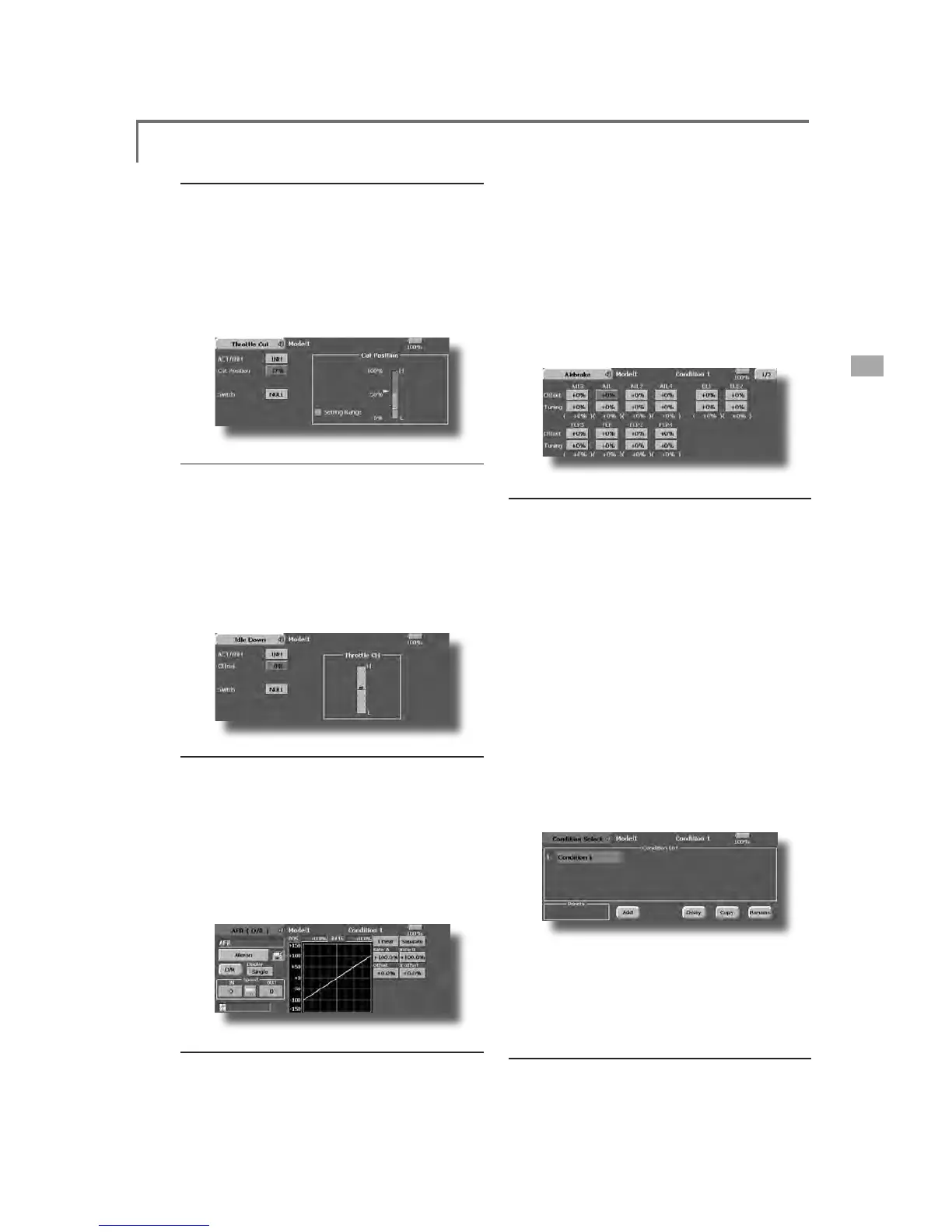
the throttle trim position.
S
et throttle cut with the Throttle
C
ut function of
t
h
e L
i
n
k
age Menu. After act
i
vat
i
ng t
h
e t
h
rott
l
e cut
function and selectin
g
the switch, ad
j
ust the throttle
p
osition so that the carburetor becomes full o
p
en. Fo
r
safety, t
h
e t
h
rott
l
e cut funct
i
on operates t
h
e t
h
rott
l
e
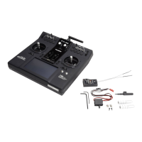
stick in the 1/3 or less (slow side)
p
osition
.
5
. Idle down sett
i
n
g
T
he idling speed can be lowered with one touch b
y
a
sw
i
tc
h
w
i
t
h
out c
h
ang
i
ng t
h
e t
h
rott
l
e tr
i
m pos
i
t
i
on.
P
erform t
hi
s sett
i
n
g
w
i
t
h
t
h
e I
dl
e Down funct
i
on of t
he
Linkage Menu. After activating the Idle Down function
a
n
d
se
l
ect
i
ng t
h
e sw
i
tc
h
, a
dj
ust t
h
e
idl
e
d
own spee
d
.
F
or safet
y
, t
h
e
idl
e
d
own funct
i
on acts on
ly
w
h
en t
h
e
throttle stick is in the 1/3 or less (slow side)
p
osition
.
*While the Throttle Cut function is in o
p
eration, the Idle
Down funct
i
on
d
oes not wor
k.
6. AFR (D/R
)
AFR funct
i
on
i
s use
d
to a
dj
ust t
h
e t
h
row an
d
op
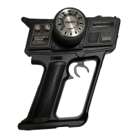
eration curve of the stick, lever, and switch functions
&+WR&+DQG9WR9IRUHDFKÀLJKWFRQGLWLRQ
T
hi
s
i
s norma
ll
y use
d
after En
d
Po
i
nt
(
ATV
)
h
as
d
efined the maximum throw directions (End Point
a
cts on ALL flight condition settings). When mixing
i
s app
li
e
d
from one c
h
anne
l
to anot
h
er c
h
anne
l
,
b
ot
h
c
hannels can be ad
j
usted at the same time b
y
ad
j
ustin
g
the operation rate through the AFR function
.
7
. Airbrake
Thi
s funct
i
on
i
s use
d
w
h
en an a
i
r
b
ra
k
e
i
s necessar
y
w
hen takin
g
off or divin
g
, etc
.
Th
e preset e
l
evators an
d
f
l
aps
(
cam
b
er f
l
ap,
b
ra
k
e
ÀDSRIIVHWDPRXQWFDQEHDFWLYDWHGE
\
DVZLWFK
7
KHRIIVHWDPRXQWRIWKHDLOHURQHOHYDWRUDQGÀD
S
servos can
b
e a
dj
uste
d
as nee
d
e
d
. A
l
so t
h
e spee
d
of t
he
DLO
HURQH
O
HYDWRUDQ
G
À
DSVHUYRVFDQ
E
HD
GM
XVWH
G

,
1
side/OUT side) A dela
y
can be set for each condition,
a
n
d
a Cut sw
i
tc
h
w
hi
c
h
w
ill
turn OFF t
h
e
d
e
l
ay can
E
HF
K
RVHQ7U
L
PDPRXQWVFDQ
E
H
¿
QHWXQH
G
E\
VHWW
L
Q
J
a
VR You can also set the Auto Mode
,
which will lin
k
Ai
r
b
ra
k
e to a st
i
c
k
, sw
i
tc
h
, or
di
a
l
. A separate st
i
c
k
VZLWFKRUGLDOFDQDOVREHVHWDVWKH212))VZLWFK
$GG
L
W
L
RQR
I
ÀL
JKWFRQG
L
W
L
RQ
V
7
KHWUDQVPLWWHUFDQLQVWDOOXSWRHL
J
KWÀL
J
KWFRQGLWLRQ
V
p
er model. You can assign all switches including sticks,
VZ
L
WF
K
HVWU
L
P
O
HYHUVDQ
G
WU
L
PVZ
L
WF
K
HVDV
ÀL
J
K
WFRQ
GL
W
L
RQ
selection switches. You can also add dela
y
ed mixin
g
to these functions in order to avoid sudden changes.
0
RUHRYHU\RXFDQVHWSU
L
RU
L
W\RU
G
HUIRU
ÀL
J
K
WFRQ
GL
W
L
RQV
w
hen
y
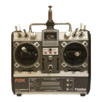
ou set more than one condition. In addition,
y
o
u
c
an copy conditions and/or change names of conditions.
7
KL
VFRPPDQ
G
PD\D
O
VR
E
HXVH
G
WR
G
H
¿
QHZ
K
DWVZ
L
WF
K
H
V
D
QGRUFRQWUROVDUHXVHGWRDFWLYDWHHDFKÀL
J
KWFRQGLWLRQ
T
he Condition Select function automatically allocates the
Con
di
t
i
on 1 for eac
h
mo
d
e
l
type. Con
di
t
i
on 1
i
s t
h
e
d
efau
lt
F
RQGLWLRQDOVRUHIHUUHGWRDV1RUPDODQGLVWKHRQO
\
RQHDFWLY
H
w
hen a new model type is defined. This condition is always on,
a
n
d
rema
i
ns on unt
il
ot
h
er con
di
t
i
ons are act
i
vate
d
b
y sw
i
tc
h
es.
Th
e Con
di
t
i
on De
l
a
y
can
b
e pro
g
ramme
d
for eac
h
c
hannel. The Condition Delay is used to change the
servo t
h
row smoot
hl
y w
h
en sw
i
tc
hi
ng con
di
t
i
ons
.
*
When a new condition is added
,
"Condition1" data is
automaticall
y
copied
.
*S
elect the condition switch and set the new condition data in th
e
V
ZLWFK21VWDWH+RZHYHULIWKH
J
URXSPRGH*UZDVVHOHFWHGL
Q
a
d
vance, t
h
e same
d
ata w
ill
b
e
i
nput at a
ll
t
h
e con
di
t
i
ons. Se
l
ect t
he
si
n
gl
e mo
d
e
(
Sn
gl)
an
d
a
dj
ust t
h
e con
di
t
i
on
y
ou want to c
h
an
g
e.
9. When ta
i
lless w
i
n
g
model selecte
d
7
DLOOHVVZLQJHOHYDWRURSHUDWLRQXVHVHOHYDWRUĺFDPEH
U
m
i
x
i
ng. T
hi
s funct
i
on cannot
b
e performe
d
at
i
n
i
t
i
a
l
sett
i
ng
.

Table of Contents

Related product manuals