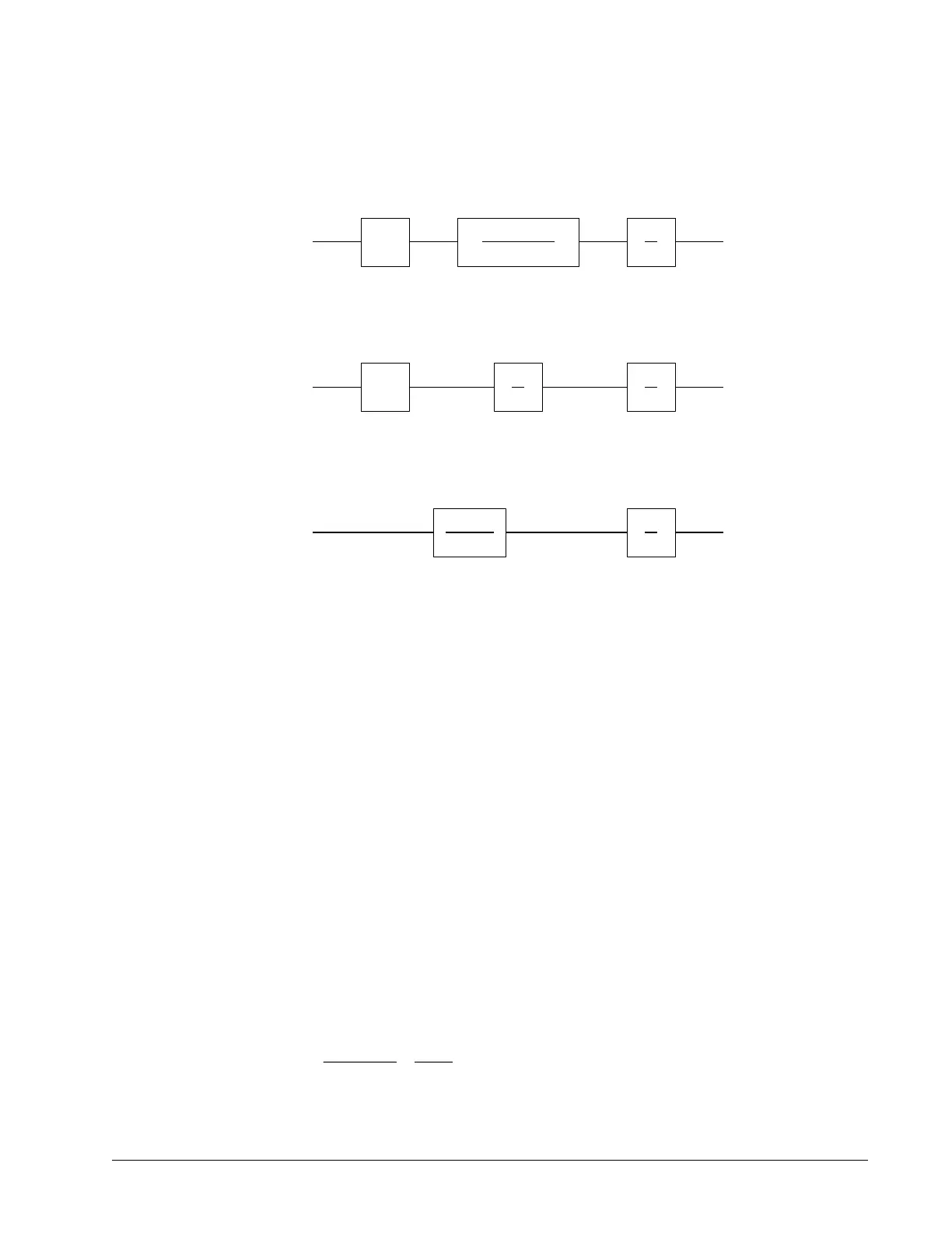
The resulting functions derived above are illustrated by the block diagram of Figure 10.6.
Figure 10.6: Mathematical model of the motor and amplifier in three operational modes
Encoder
The encoder generates N pulses per revolution. It outputs two signals, Channel A and B, which are in quadrature.
Due to the quadrature relationship between the encoder channels, the position resolution is increased to 4N
quadrature counts/rev.
The model of the encoder can be represented by a gain of
K
f
= 4N/2π [count/rad]
For example, a 1000 lines/rev encoder is modeled as
K
f
= 638
DAC
The DAC or D-to-A converter converts a 16-bit number to an analog voltage. The input range of the numbers is
65536 and the output voltage range is ±10V or 20V. Therefore, the effective gain of the DAC is
K= 20/65536 = 0.0003 [V/count]
Digital Filter
The digital filter has three element in series: PID, low-pass and a notch filter. The transfer function of the filter. The
transfer function of the filter elements are:
PID D(z) =
Chapter 10 Theory of Operation ▫ 175 DMC-40x0 User Manual
K
v
1/K
e
(ST
m
+1)(ST
e
+1)
1
S
V
E W P
VOLTAGE SOURCE
K
a
K
t
JS
1
S
V
I W P
CURRENT SOURCE
1
S
V
W P
VELOCITY LOOP
1
K
g
(ST
1
+1)

 Loading...

