9 AA- Clock - (Cn- or MA-)
10 HALA A Channel Hall Sensor
11 AA+ Clock + (Cn+ or MA+)
12 AB- Data - (Dn- or SLO-)
13 HALB B Channel Hall Sensor
14 HALC C Channel Hall Sensor
15 +5V +5V
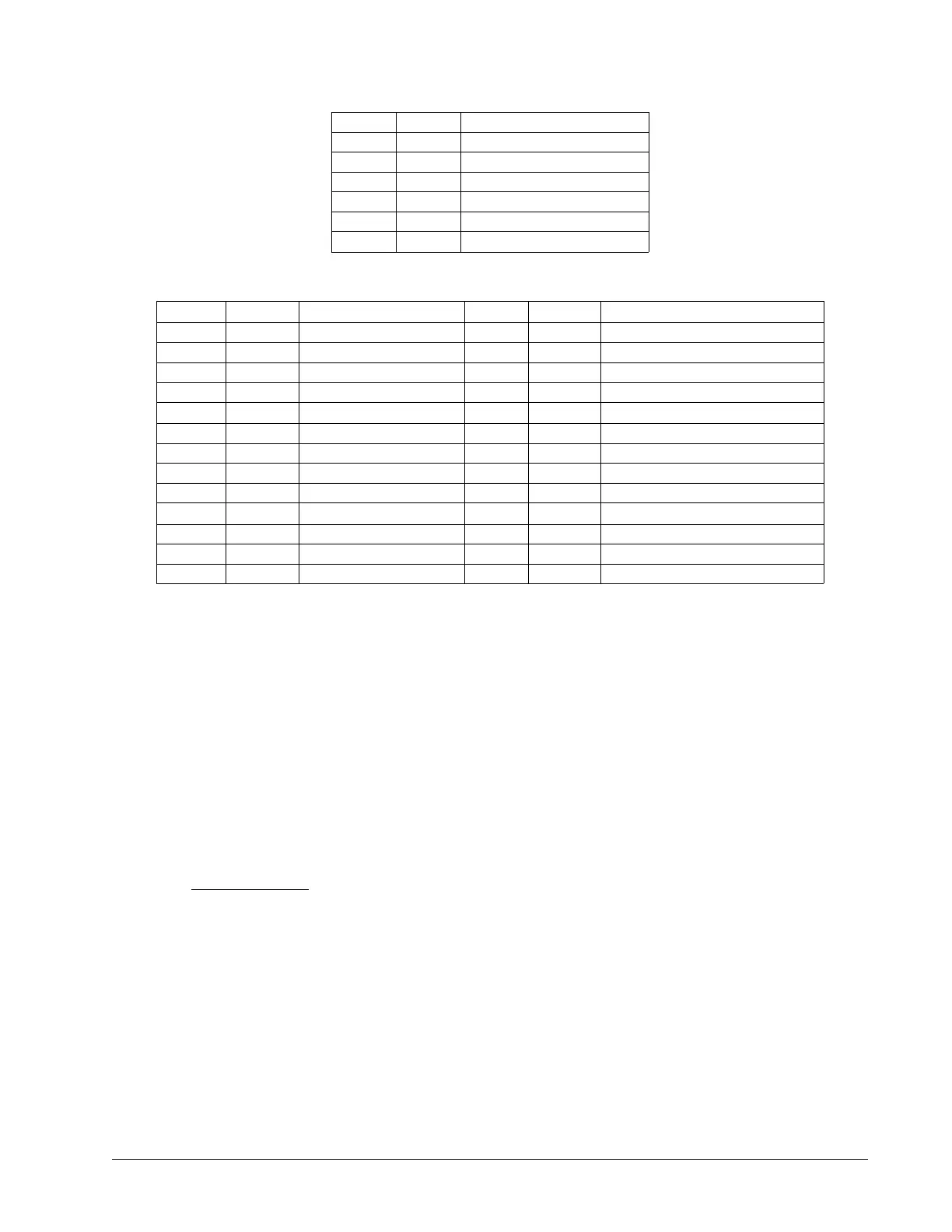
ICM-42200 Encoder 26 pin HD D-Sub Connector (BiSS or SSI Option)
Pin # Label Description Pin # Label Description
1 RES Reserved / Hall 2 14 FLS Forward Limit Switch Input
2 AEN Amplifier Enable 15 AB+ Data + (Dn+ or SLO+)
3 DIR Direction 16 MI- I- Index Pulse Input
4 HOM Home 17 MB+ B+ Main Encoder Input
5 LSCOMn Limit Switch Common
2
18 GND
Digital Ground
1
6 AA- Clock - (Cn- or MA-) 19 MCMD Motor Command
7 MI+ I+ Index Pulse Input 20 ENBL+ Amp Enable Power
8 MA- A- Main Encoder Input 21 RES Reserved / Hall 0 / Step_N
9 +5V +5V 22 RLS Reverse Limit Switch Input
10 GND
Digital Ground
1
23 AB- Data - (Dn- or SLO-)
11 ENBL- Amp Enable Return 24 AA+ Clock + (Cn+ or MA+)
12 RES Reserved / Hall 1/ Dir_N 25 MB- B- Main Encoder Input
13 STP PWM/Step 26 MA+ A+ Main Encoder Input
1
Only one ground pin must be connected to the encoders digital ground signal.
2
LSCOMn on JA1, JB1, JC1 and JD1 is common to LSCOM0 on J5
LSCOMn on JE1, JF1, JG1 and JH1 is common to LSCOM1 on J8
Note: This option is not valid with the ICM-42100 (-I100). Consult Galil if the Sinusoidal encoder and SSI encoder
interfaces are required on the same set of 4 axes.
Part number ordering example: DMC-4010-C012-I000(SSI)
Amplifier Enable Configurations
The default amplifier enable configuration for the ICM interconnect modules is 5V, HAEN, SINK. This is 5V logic,
high amplifier enable, and sinking. The amplifier enable configuration can be configured at the factory or in the
field. It is recommended that the correct amplifier enable configuration be ordered from the factory when using
the ICM-42000 (-I000) or the ICM-42100 (-I100). The Galil internal amplifiers will work with any amplifier enable
configurations set on the interconnect module.
See the Amplifier Interface section in Chapter 3 for more information.
Part number ordering example: DMC-4010-C012-I000(24V,HAEN,SINK)
5V – 5V Amplifier Enable Voltage
Uses the DMC-40x0 internal 5V for the amplifier enable circuit.
12V – 12V Amplifier Enable Voltage
Uses the DMC-40x0 internal 12V for the amplifier enable circuit.
Appendices ▫ 189 DMC-40x0 User Manual

 Loading...

