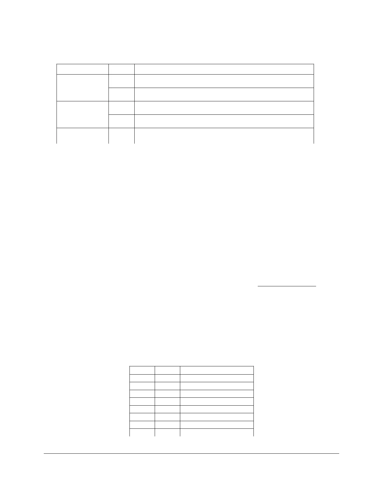
RS-232/422 Configuration Jumpers
Location Label Function (If jumpered)
JP2 (-C012, default)
JP3 (-C022)
ARXD Connects a 120 Ω Termination resistor between the differential “Receive”
inputs on the Aux Serial port. Pins 2 and 7 on RS-422 Auxiliary Port.
ACTS Connects a 120 Ω Termination resistor between the differential “Clear To
Send” inputs on the Aux Serial port. Pins 1 and 6 on RS-422 Auxiliary Port.
JP2 (-C012, default)
JP2 (-C022)
MRXD Connects a 120 Ω Termination resistor between the differential “Receive”
inputs on the Main Serial port. Pins 3 and 8 on RS-422 Main Port.
MCTS Connects a 120 Ω Termination resistor between the differential “Clear To
Send” inputs on the Main Serial port. Pins 4 and 9 on RS-422 Main Port.
JP2 (-CO12, default)
JP3 (-C022)
APWR Do not use with RS-422 option.
Note: The ARXD, ACTS, MRXD and MCTS should be installed for single-drop RS-422. For
multi-drop, the jumpers should be installed on the last device.
ICM, “-IXXX(Y)” Interconnect Board Options
The following options are the “Y” configuration options that can be added to the -IXXX part number. Multiple Y-
options can be ordered per board.
DIFF – Differential analog motor command outputs
The DIFF option configures the ICM interconnect module with differential analog motor command outputs. Single-
ended motor command outputs are standard. See the individual ICM sections in Integrated Components for pinout
information.
Part number ordering example: DMC-4010-C012-I000(DIFF)
STEP – Differential step and direction outputs
The STEP option configures the ICM interconnect module with differential step and direction outputs. Single-
ended step and direction outputs are standard. See the individual ICM sections in Integrated Components for
pinout information.
Part number ordering example: DMC-4010-C012-I000(STEP)
SSI and BiSS – SSI and BiSS Absolute encoder Option
The BiSS and SSI options configures the ICM interconnect module for BiSS or SSI absolute encoder inputs. See the
SS and SI commands in the DMC-40x0 Command Reference. Pin-out information is shown below for the ICM-
42000 and the ICM-42200.
ICM-42000 Encoder 15 pin HD D-Sub Connector (BiSS or SSI Option)
Pin # Label Description
1 MI+ I+ Index Pulse Input
2 MB+ B+ Main Encoder Input
3 MA+ A+ Main Encoder Input
4 AB+ Data + (Dn+ or SLO+)
5 GND Digital Ground
6 MI- I- Index Pulse Input
7 MB- B- Main Encoder Input
8 MA- A- Main Encoder Input
Appendices ▫ 188 DMC-40x0 User Manual

 Loading...

