The placement of ICM and AMP/SDM options is extremely important for 5-8 axis models. Reading left to right, the
first ICM (Axis 1-4) will be placed in the ICM (1) spot in Figure 1.2 and the second ICM (Axis 5-8) will be placed in
the ICM (2) spot. This also follows for AMP/SDM placement.
If the part number is not readily available, you can determine the information by using the 'ID' command. Issuing
an 'ID' command when connected to the controller will return your controller's internal hardware configuration.
WARNING
The CMB and ICM module options effect the pin-outs of the DMC-40x0.
Use Table 1.2 and Table 1.3 below to determine your CMB and ICM part numbers then refer to the
appropriate documentation for your pin-outs before connecting any hardware.
DMC, “DMC-40X0(Y)” Options
Option Type Options
Brief Description Documentation
X 1,2,3,4,5,6,7, and 8 Number of control axis N/A
Y DIN DIN Rail Mount DMC, “DMC-40X0(Y)” Controller Board
Options, starting on pg 185.
12V Power Controller with 12 VDC
-16bit 16-bit analog inputs
4-20mA 4-20mA analog inputs
ISCNTL Isolate Controller Power
TRES Encoder terminating resistors
ETL ETL certification
MO Motor off jumper installed
Table 1.1: Controller board, DMC, “DMC-40X0(Y)” options
Chapter 1 Overview ▫ 3 DMC-40x0 User Manual
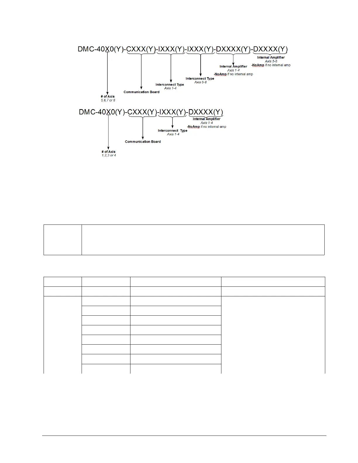
Figure 1.3: Layout of a complete DMC-40x0 part number

 Loading...

