Concord 10
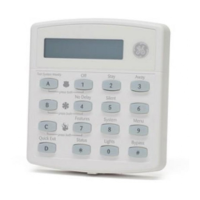
Figure 2. Mounting the Panel
Identify Panel
Components
Before installing devices and making wiring connections, familiarize yourself with the main
panel components. Figure 3 shows the main component locations for the hardwire circuit board
and the main component locations for the combination hardwire/wireless circuit board.
Figure 3. Hardwire and Combination Hardwire/Wireless Circuit Board Main Components
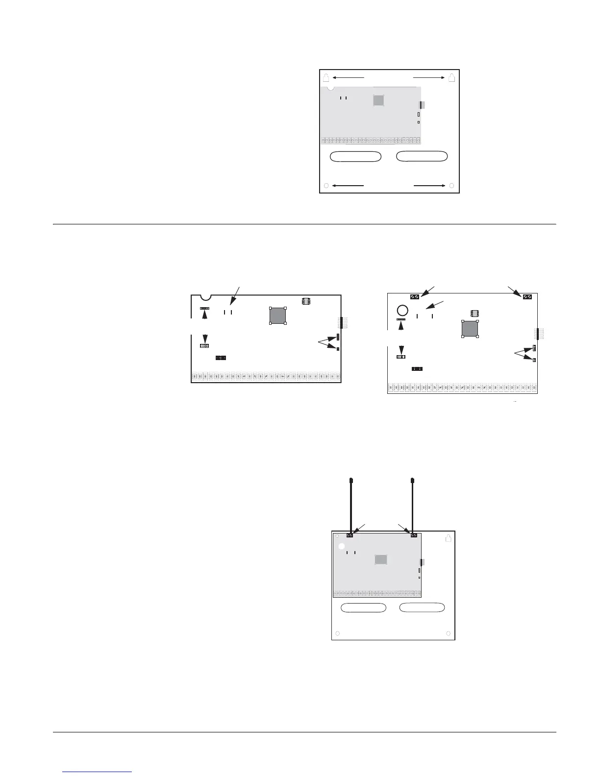
Installing Antennas
Install the antennas (included with panel) into the inside terminal of each antenna terminal block
on the combination hardwire/wireless panel (see Figure 4).
Figure 4. Installing the Antennas
Knockout Knockout
Mounting
Holes
Mounting
Holes
6 0 7 3 4 G 1 0 D . D S F
Backup Battery Connections
Red
Black
Power Line Carrier
Card Headers
Micro
Processor
EEPROM
SnapCard
Header
Phone
Supervision
Card Headers
Terminal Strip
Programming
Touchpad
Header
6 0 7 3 4
2 0 6 d . d s f
Backup Battery Connections
Antenna Terminal Blocks
RedBlack
Power Line Carrier
Card Headers
Programming
Touchpad
Header
Micro
Processor
EEPROM
Phone
Supervision
Card Headers
SnapCard
Header
Terminal Strip
Connect
To Inside
Terminal