Concord
23
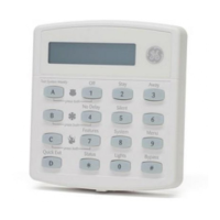
3. Check the phones on the premises for dial tone and the ability to dial out and make phone
calls. If phones do not work correctly, check all wiring and correct where necessary. Proceed
to the “Troubleshooting” section of this manual if problems persist.
Figure 27. Connecting an RJ-31X Jack and DB-8 Cord
Connecting the AC Power Transformer
The panel must be powered by a plug-in stepdown transformer that supplies 24 VAC, 30 VA (60-
761) or 24 VAC, 50 VA (60-778).
For systems that include a Power Line Carrier card and Supervised Wireless Sirens, or X10
Lamp Modules, the panel must be powered with the Line Carrier Power Transformer that sup-
plies 24 VAC, 30 VA (60-762) or 24 VAC, 50 VA (60-779). Connect the power transformer to the
panel as shown in Figure 28.
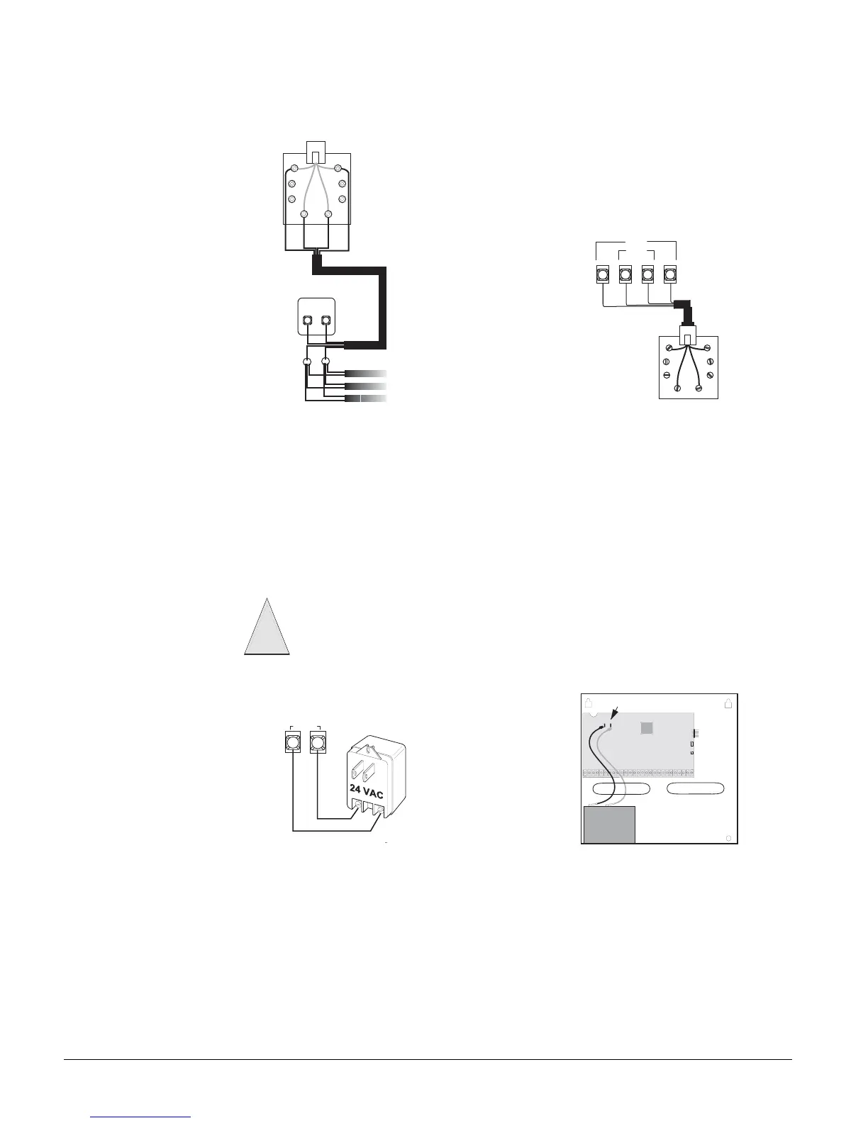
Figure 28. Connecting a Power Transformer and Backup Battery
Powering Up the Panel
After connecting and wiring all devices to the panel, you are ready to apply AC and backup bat-
tery power to the panel.
¾
To power up the panel (see Figure 28):
1. Connect the red and black battery leads (included with panel) to the lugs on the panel.
2. Connect the other ends of the battery leads to the battery terminals.
3. Plug the transformer into an outlet that is not controlled by a switch.
0 7 3 4 G 8 4 D . D S F
R I N G
( - )
T I P
( + )
A
B
C
D
2 5
2 6 2 7
6 0 7 3 4 G 8 6 D . D S F
2 4
Gry
Brn
Red
Grn
Jack
RJ-31X
Black
Green
Red
White
(or Yellow)
(or Yellow)
White
Red
Black
Green
Green
Red
TELCO
Protector Block
RJ-31X
Phone
Line
Wire
Run
Lines From
Phones On
Premises
Brn GryGrn Red
Red
Gray
Brown
Green
Brn Gry
Grn Red
RJ-31X
Jack
TELCO
House
DB-8 Cord
Do not plug in the power transformer at this time. The panel must be powered up using
the sequence of steps described in the next section, “Powering Up the Panel.”
Caution
!
1
2
6 0 7 3 4 g 1 0 4 d . d s f
2 4 V A C
Panel Terminals
Backup Battery Connections
Battery
Red
Black
Red
Black