Concord 12
Installing Optional SnapCards
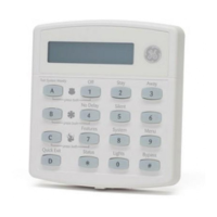
The SnapCard Header on the right side of the panel allows for the installation of one SnapCard.
Install the desired SnapCard onto the panel SnapCard Header and secure it in place with two
screws, included with the card (see Figure 8).
Connect all necessary input/output wiring using the Installation Instructions included with the
card.
Figure 8. Installing a SnapCard into the Panel Expansion Connector
Note
The panel comes with fac-
tory programmed onboard
hardwire zones. Install
2k-ohm, end of line (EOL)
resistors on all unused fac-
tory programmed onboard
hardwire zones. If you don’t
want to install EOL resistors,
delete any unused zones
from memory. See Table 8
for onboard hardwire zone
factory programming.
Connecting Detection Devices to Panel Zone Inputs
Zone inputs 1 through 8 are supervised using included 2k-ohm, end-of-line resistors at the last
device on each circuit. All eight zones accept either normally open (N/O) or normally closed (N/
C) detection devices.
Connecting Intrusion Detection Devices
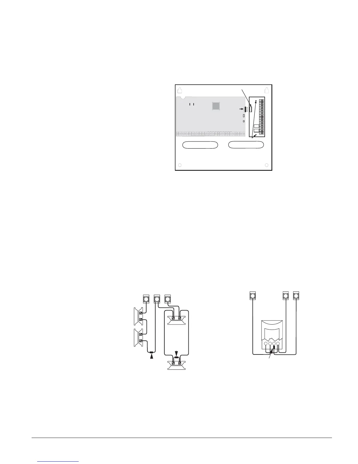
Figure 9 shows the typical wiring for N/C and N/O door/window intrusion detection and the typ-
ical wiring for a Detection Systems model DS922 (part no. 13-082) motion detector. The mini-
mum available panel voltage for hardwired PIR motion detectors is 8.5 VDC (9.5 VDC for UL
listed installations).
Note
When using 2-wire smoke detectors on zone 8, the Two-Wire Smoke setting (in program mode) must be
turned on before entering the
LEARN SENSORS menu. See ONBOARD OPTIONS—INPUTS in the section
“Programming the Panel” for complete details.
Figure 9. Connecting N/C and N/O Intrusion Detection and Motion Detector Circuits to the Panel
Connecting 2-Wire Smoke Detectors
Zone input 8 can be set up (in program mode) to accept the following 12 VDC, 2-wire smoke
detectors:
• System Sensor models 2100D, 2100TD, 2100S, 2100TS, 2400, 2400TH
Connector
SnapCard
Screw Locations
SnapCard
Header
Panel Terminals
2k Ohm EOL
Resistor 49-454
Normally Open
(N/O) Contacts in
Parallel
2k Ohm EOL
Resistor 49-454
Normally
Closed
(N/C)
Contacts
In Series
Zone 2
GND
Zone 3
Panel
Terminals
2k Ohm EOL Resistor 49-454
(Locate at Sensor)
+12
BUS
GND
Zone
7
Motion
Detector