Concord 18
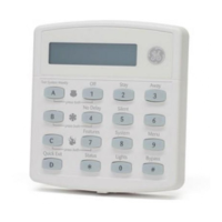
Figure 16. Connecting Touchpads to the Panel
Installing SuperBus 2000 Modules
SuperBus 2000 modules can be installed inside the panel cabinet or away from the panel. Use the
following guidelines when installing modules inside the panel cabinet (see Figure 17):
• Up to 16 bus modules can be connected to the panel. (15 modules for the RF panel since
receiver counts as 1.)
• Up to 3 of the SuperBus 2000 modules listed in Table 1 can be mounted inside the cabinet.
• The panel includes two support standoffs you install to secure module backplates to the
panel.
Note
Even if you don’t plan to
mount modules inside the
cabinet, install the support
standoffs for future use and
to avoid losing them.
• Install the standoffs at the locations shown.
• The cabinet has built-in mounting clips on the top and sides that module backplates slide
onto for mounting.
• One SuperBus 2000 RF Receiver can be installed inside the cabinet, but it must be mounted
on the right-hand side to accommodate the antennas. Additional receivers must be installed
outside the cabinet.
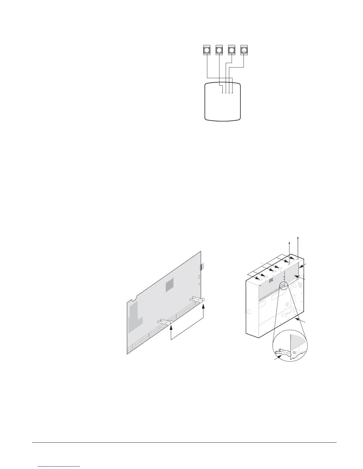
Figure 17. Installing SuperBus 2000 Modules (RF Receiver Shown)
SuperBus 2000 RF Receiver (60-764-01-95R-16Z/32Z/MAX)
1. Mount the receiver inside the cabinet enclosure as shown in Figure 17.
2. Connect the receiver to the panel as shown in Figure 18.
SuperBus 2000
Fixed Display
Touchpad or
LCD Alphanumeric
Touchpads
+12V/Red
Bus A/Green
Bus B/White
GND/Black
GND
+12V A Bus B
3456
6 0 7 3 4 g 1 0 7 d . d s f
Support
Support Standoff
Standoffs
Side
Mounting
Clip
Panel
Cabinet
RF
Receiver
Module
(Cover
Removed)
Top
Mounting
Clips (6)