Simon XT
Installation Manual
20
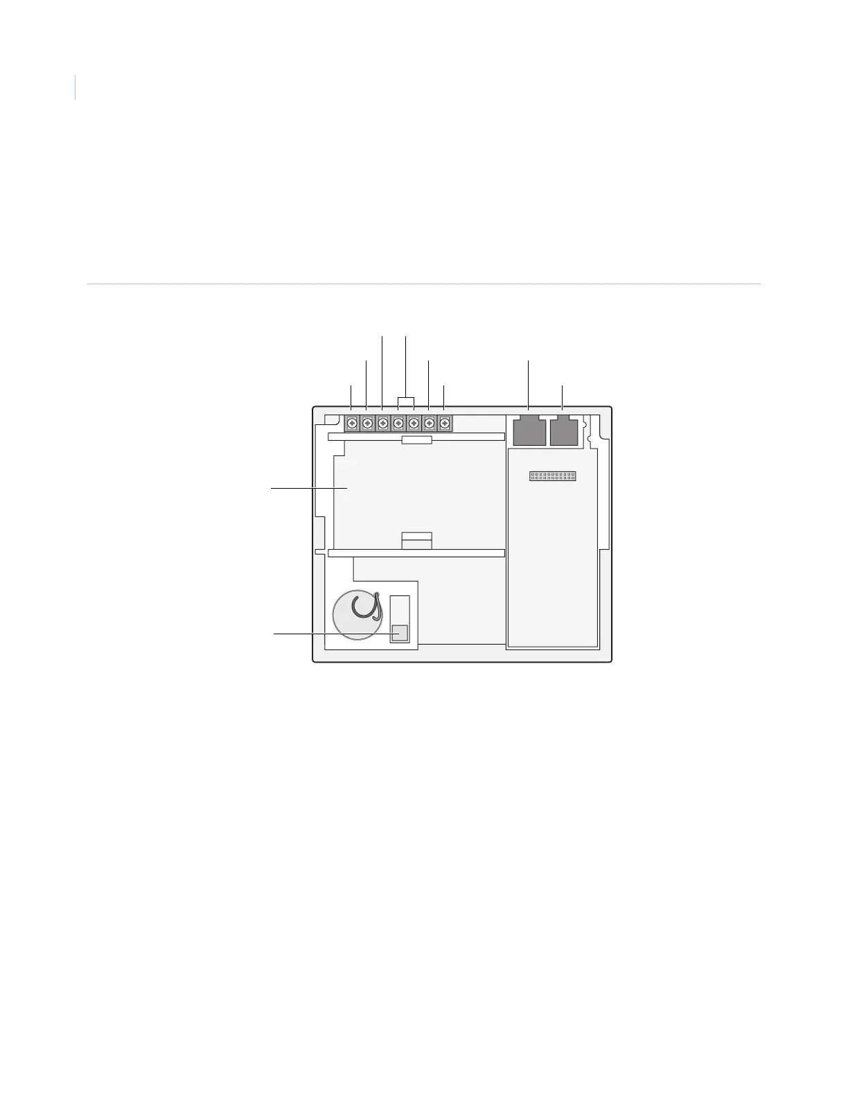
Connecting hardwired devices
The panel has seven screw terminals and two telephone connections (Figure 5). The screw terminals connect
AC power, sirens, and/or hardwired detectors.
Program sensors and devices before you install them. Follow the instructions in Chapter 4 Programming to
add the sensors to panel memory.
Figure 5. Simon XT terminal connections
HW1 I/O, HW2 in, and HW1&2 DC out terminals
The HW1 I/O terminal is dual purpose and can be used for either siren or hardwired contact connections. The
HW2 in terminal is an input only.
Interior sirens
From the factory, the HW1 I/O input is set up for interior siren operation (status and alarm sounds). HW1&2
DC out provides the positive (+) voltage.
Note: The total current available from the HW1&2 DC out terminal is 250 mA at up to 122°F (50°C).
With Hardwired Siren Supervision turned on, sirens connected to HW1 I/O are supervised and require a
4.7 kohm resistor in the circuit. If this terminal is not used, turn Hardwired Siren Supervision off.
9 VAC in
Battery –
Battery compartment
Battery +
HW1&2 DC out
HW2 in
HW1 I/O
RJ11 connector (PHONE)
RJ45 connector (LINE)
Tamper switch