GE Power Management 750/760 Feeder Management Relay 15-
7
15 S8 TESTING 15.4 SIMULATION
15
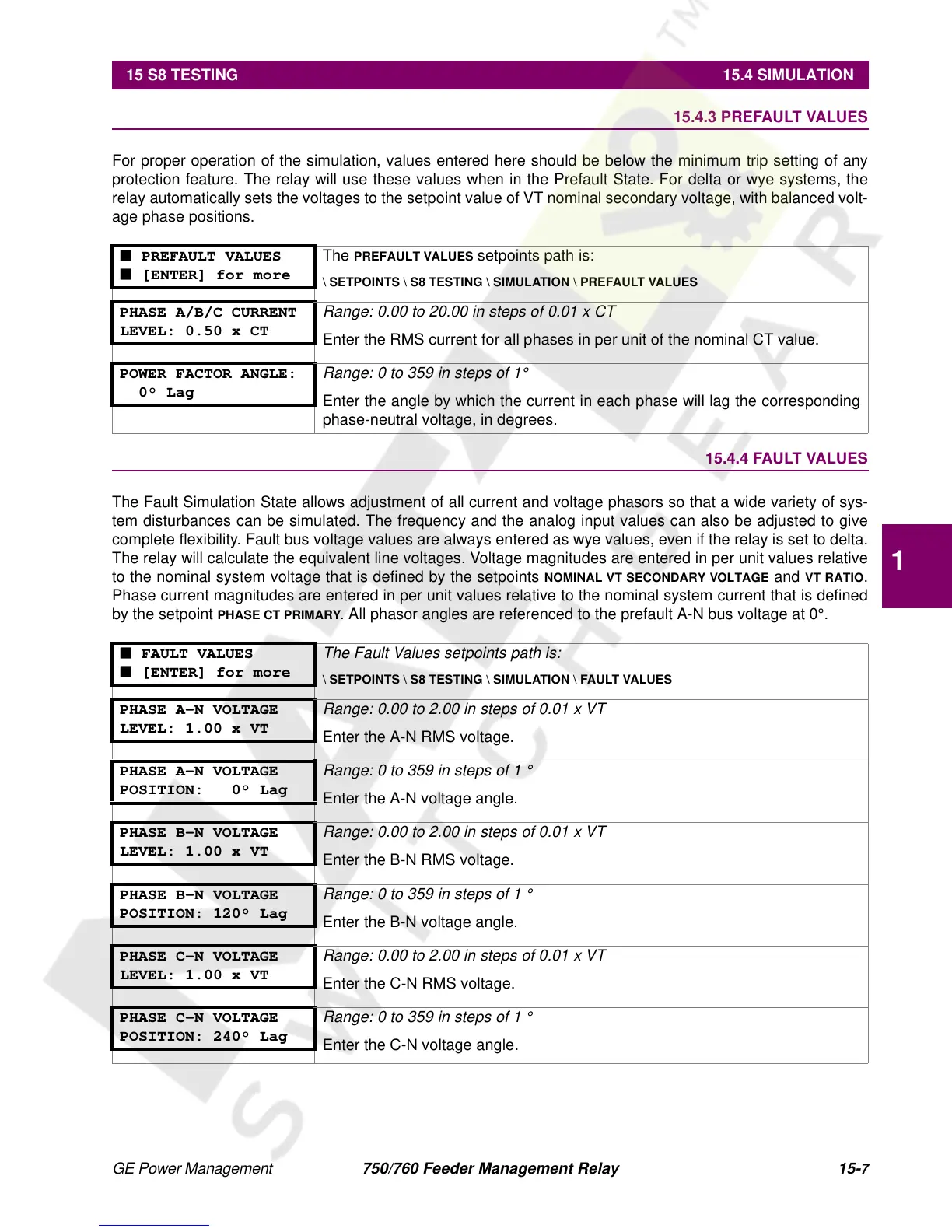
15.4.3 PREFAULT VALUES
For proper operation of the simulation, values entered here should be below the minimum trip setting of any
protection feature. The relay will use these values when in the Prefault State. For delta or wye systems, the
relay automatically sets the voltages to the setpoint value of VT nominal secondary voltage, with balanced volt-
age phase positions.
15.4.4 FAULT VALUES
The Fault Simulation State allows adjustment of all current and voltage phasors so that a wide variety of sys-
tem disturbances can be simulated. The frequency and the analog input values can also be adjusted to give
complete flexibility. Fault bus voltage values are always entered as wye values, even if the relay is set to delta.
The relay will calculate the equivalent line voltages. Voltage magnitudes are entered in per unit values relative
to the nominal system voltage that is defined by the setpoints
NOMINAL VT SECONDARY VOLTAGE
and
VT RATIO
.
Phase current magnitudes are entered in per unit values relative to the nominal system current that is defined
by the setpoint
PHASE CT PRIMARY
. All phasor angles are referenced to the prefault A-N bus voltage at 0°.
■ PREFAULT VALUES
■ [ENTER] for more
The
PREFAULT VALUES
setpoints path is:
\ SETPOINTS \ S8 TESTING \ SIMULATION \ PREFAULT VALUES
PHASE A/B/C CURRENT
LEVEL: 0.50 x CT
Range: 0.00 to 20.00 in steps of 0.01 x CT
Enter the RMS current for all phases in per unit of the nominal CT value.
POWER FACTOR ANGLE:
0° Lag
Range: 0 to 359 in steps of 1°
Enter the angle by which the current in each phase will lag the corresponding
phase-neutral voltage, in degrees.
■ FAULT VALUES
■ [ENTER] for more
The Fault Values setpoints path is:
\ SETPOINTS \ S8 TESTING \ SIMULATION \ FAULT VALUES
PHASE A-N VOLTAGE
LEVEL: 1.00 x VT
Range: 0.00 to 2.00 in steps of 0.01 x VT
Enter the A-N RMS voltage.
PHASE A-N VOLTAGE
POSITION: 0° Lag
Range: 0 to 359 in steps of 1 °
Enter the A-N voltage angle.
PHASE B-N VOLTAGE
LEVEL: 1.00 x VT
Range: 0.00 to 2.00 in steps of 0.01 x VT
Enter the B-N RMS voltage.
PHASE B-N VOLTAGE
POSITION: 120° Lag
Range: 0 to 359 in steps of 1 °
Enter the B-N voltage angle.
PHASE C-N VOLTAGE
LEVEL: 1.00 x VT
Range: 0.00 to 2.00 in steps of 0.01 x VT
Enter the C-N RMS voltage.
PHASE C-N VOLTAGE
POSITION: 240° Lag
Range: 0 to 359 in steps of 1 °
Enter the C-N voltage angle.

 Loading...


