15-
8
750/760 Feeder Management Relay GE Power Management
15.4 SIMULATION 15 S8 TESTING
15
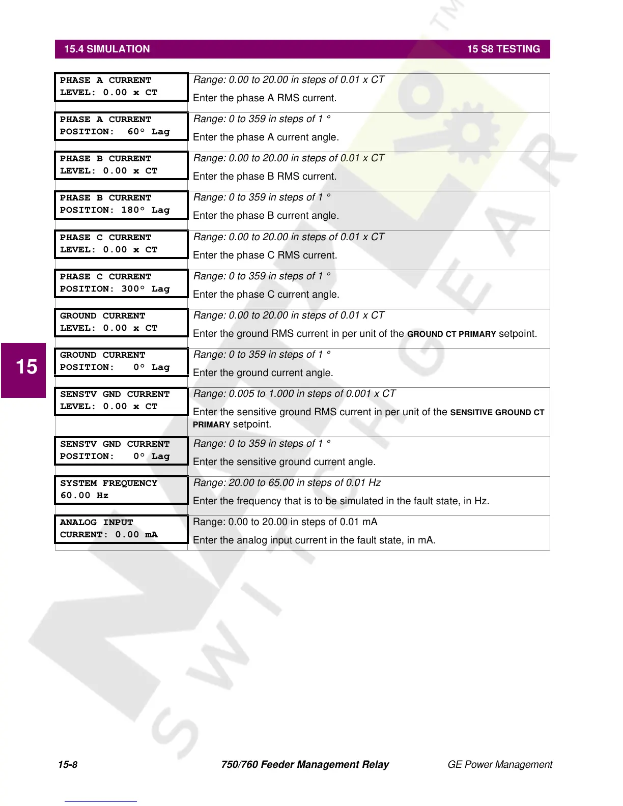
PHASE A CURRENT
LEVEL: 0.00 x CT
Range: 0.00 to 20.00 in steps of 0.01 x CT
Enter the phase A RMS current.
PHASE A CURRENT
POSITION: 60° Lag
Range: 0 to 359 in steps of 1 °
Enter the phase A current angle.
PHASE B CURRENT
LEVEL: 0.00 x CT
Range: 0.00 to 20.00 in steps of 0.01 x CT
Enter the phase B RMS current.
PHASE B CURRENT
POSITION: 180° Lag
Range: 0 to 359 in steps of 1 °
Enter the phase B current angle.
PHASE C CURRENT
LEVEL: 0.00 x CT
Range: 0.00 to 20.00 in steps of 0.01 x CT
Enter the phase C RMS current.
PHASE C CURRENT
POSITION: 300° Lag
Range: 0 to 359 in steps of 1 °
Enter the phase C current angle.
GROUND CURRENT
LEVEL: 0.00 x CT
Range: 0.00 to 20.00 in steps of 0.01 x CT
Enter the ground RMS current in per unit of the
GROUND CT PRIMARY
setpoint.
GROUND CURRENT
POSITION: 0° Lag
Range: 0 to 359 in steps of 1 °
Enter the ground current angle.
SENSTV GND CURRENT
LEVEL: 0.00 x CT
Range: 0.005 to 1.000 in steps of 0.001 x CT
Enter the sensitive ground RMS current in per unit of the
SENSITIVE GROUND CT
PRIMARY
setpoint.
SENSTV GND CURRENT
POSITION: 0° Lag
Range: 0 to 359 in steps of 1 °
Enter the sensitive ground current angle.
SYSTEM FREQUENCY
60.00 Hz
Range: 20.00 to 65.00 in steps of 0.01 Hz
Enter the frequency that is to be simulated in the fault state, in Hz.
ANALOG INPUT
CURRENT: 0.00 mA
Range: 0.00 to 20.00 in steps of 0.01 mA
Enter the analog input current in the fault state, in mA.

 Loading...


