GE Power Management 750/760 Feeder Management Relay 16-
81
16 COMMUNICATIONS 16.4 MODBUS MEMORY MAP
16
76
1
Zero Sequence Voltage Angle
77
3
Sensitive Ground Current
78
3
Sensitive Ground Current Angle
79
4
Neutral Voltage
80
4
Neutral Voltage Angle
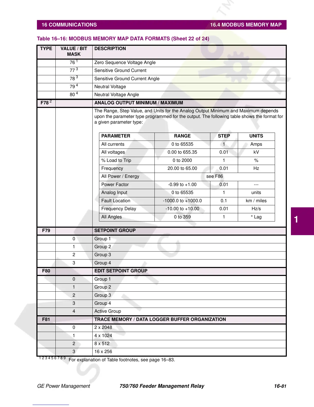
F78
2
ANALOG OUTPUT MINIMUM / MAXIMUM
The Range, Step Value, and Units for the Analog Output Minimum and Maximum depends
upon the parameter type programmed for the output. The following table shows the format for
a given parameter type:
F79 SETPOINT GROUP
0 Group 1
1 Group 2
2 Group 3
3 Group 4
F80 EDIT SETPOINT GROUP
0 Group 1
1 Group 2
2 Group 3
3 Group 4
4 Active Group
F81 TRACE MEMORY / DATA LOGGER BUFFER ORGANIZATION
0 2 x 2048
1 4 x 1024
28 x 512
3 16 x 256
Table 16–16: MODBUS MEMORY MAP DATA FORMATS (Sheet 22 of 24)
TYPE VALUE / BIT
MASK
DESCRIPTION
1 2 3 4 5 6 7 8 9
For explanation of Table footnotes, see page 16–83.
PARAMETER RANGE STEP UNITS
All currents 0 to 65535 1 Amps
All voltages 0.00 to 655.35 0.01 kV
% Load to Trip 0 to 2000 1 %
Frequency 20.00 to 65.00 0.01 Hz
All Power / Energy see F86
Power Factor -0.99 to +1.00 0.01 ---
Analog Input 0 to 65535 1 units
Fault Location -1000.0 to +1000.0 0.1 km / miles
Frequency Delay -10.00 to +10.00 0.01 Hz/s
All Angles 0 to 359 1 ° Lag

 Loading...


