16-
82
750/760 Feeder Management Relay GE Power Management
16.4 MODBUS MEMORY MAP 16 COMMUNICATIONS
16
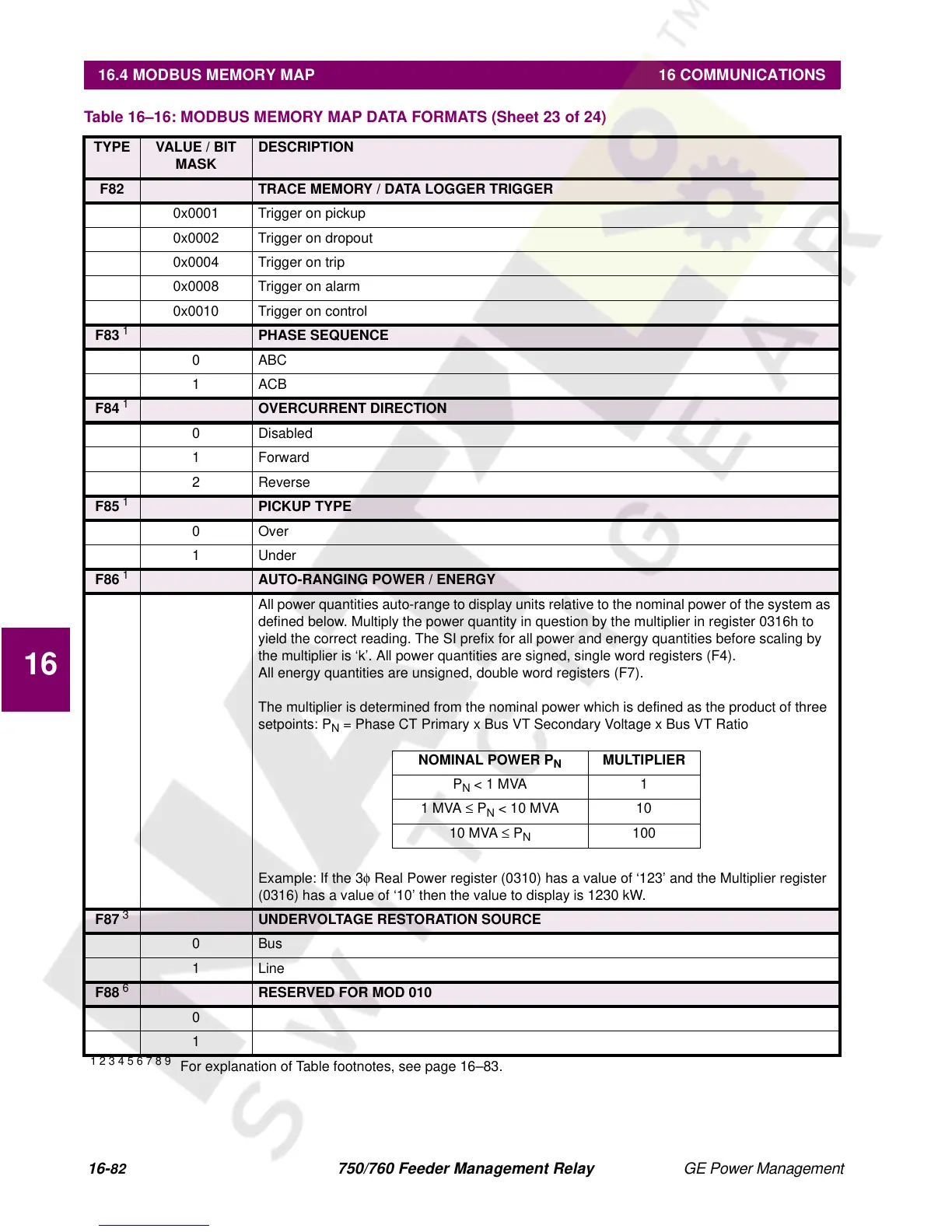
F82 TRACE MEMORY / DATA LOGGER TRIGGER
0x0001 Trigger on pickup
0x0002 Trigger on dropout
0x0004 Trigger on trip
0x0008 Trigger on alarm
0x0010 Trigger on control
F83
1
PHASE SEQUENCE
0 ABC
1ACB
F84
1
OVERCURRENT DIRECTION
0 Disabled
1Forward
2 Reverse
F85
1
PICKUP TYPE
0Over
1 Under
F86
1
AUTO-RANGING POWER / ENERGY
All power quantities auto-range to display units relative to the nominal power of the system as
defined below. Multiply the power quantity in question by the multiplier in register 0316h to
yield the correct reading. The SI prefix for all power and energy quantities before scaling by
the multiplier is ‘k’. All power quantities are signed, single word registers (F4).
All energy quantities are unsigned, double word registers (F7).
The multiplier is determined from the nominal power which is defined as the product of three
setpoints: P
N
= Phase CT Primary x Bus VT Secondary Voltage x Bus VT Ratio
Example: If the 3φ Real Power register (0310) has a value of ‘123’ and the Multiplier register
(0316) has a value of ‘10’ then the value to display is 1230 kW.
F87
3
UNDERVOLTAGE RESTORATION SOURCE
0Bus
1Line
F88
6
RESERVED FOR MOD 010
0
1
Table 16–16: MODBUS MEMORY MAP DATA FORMATS (Sheet 23 of 24)
TYPE VALUE / BIT
MASK
DESCRIPTION
1 2 3 4 5 6 7 8 9
For explanation of Table footnotes, see page 16–83.
NOMINAL POWER P
N
MULTIPLIER
P
N
< 1 MVA 1
1 MVA ≤ P
N
< 10 MVA 10
10 MVA ≤ P
N
100

 Loading...


