CHAPTER 4: INTERFACES FRONT PANEL INTERFACE
B90 LOW IMPEDANCE BUS DIFFERENTIAL SYSTEM – INSTRUCTION MANUAL 4-15
4
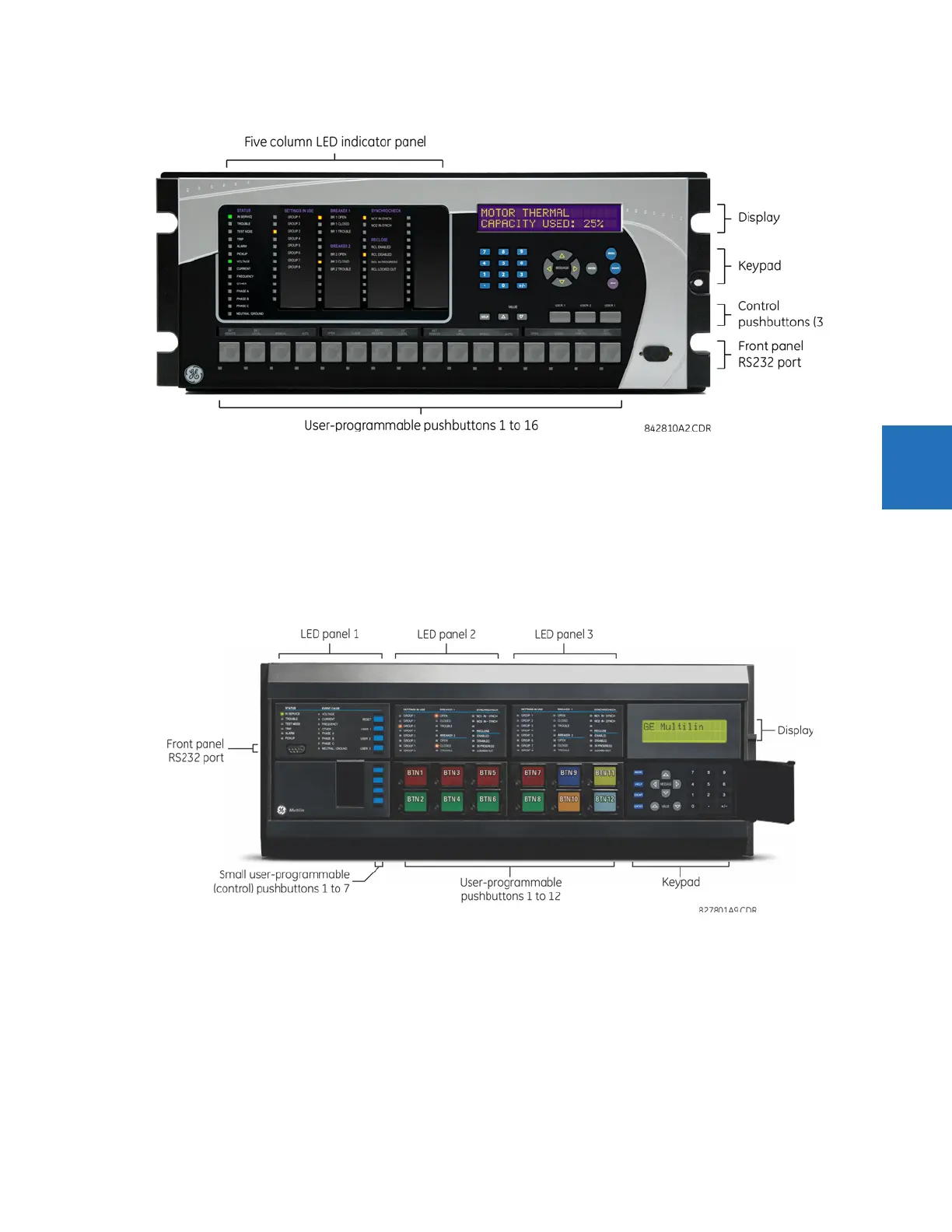
Figure 4-17: Enhanced front panel
4.2.1.2 Standard front panel
The standard front panel consists of LED panels, an RS232 port, keypad, LCD display, control pushbuttons, and optional
user-programmable pushbuttons.
The front panel is hinged to allow easy access to removable modules inside the chassis. There is also a removable dust
cover that is to be removed when accessing the keypad. The standard front panel can be horizontal or vertical. The
following figure shows the horizontal front panel.
Figure 4-18: Standard horizontal front panel
4.2.1.3 Graphical front panel
The graphical front panel consists of a USB port, LED panel, color screen display, user-programmable pushbuttons, and
navigation keys. The screen is used to read data, such as metering actual values, alarms, self-test messages, and event
records, and for viewing single-line diagrams. Settings can be changed on the front panel except for the graphical front
panel itself and for IEC 61850. The USB port connects to a computer with the EnerVista software and can be used to
upgrade the relay and to transfer files and settings. The USB port is the square type B.
User-programmable pushbuttons 9 to 16 can be programmed among the 10 pushbuttons on the left and right sides of the
display.