8-10 B90 LOW IMPEDANCE BUS DIFFERENTIAL SYSTEM – INSTRUCTION MANUAL
BUS DIFFERENTIAL SETTINGS CHAPTER 8: APPLICATION OF SETTINGS
8
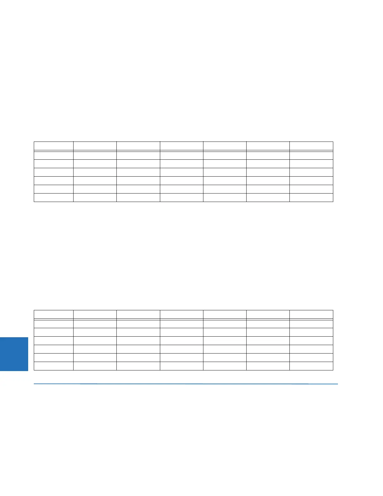
8.4.5 External faults on C-4
The following table presents the results of analysis of an external fault on circuit C-4 (C-4 is connected to the North bus; C-
3 and C-5 are connected to the South bus).
By comparing the secondary currents (column 3 in the table below) with the limits of linear operation for the CTs (column 4
in the Limits of Linear Operations of the CTs table shown earlier), it is concluded that none of the CTs saturate due to the AC
currents during this fault.
Columns 6 and 7 of the following table summarize the DC saturation threat for the fault on C-4. CT-4, CT-6, CT-7, and CT-8
can saturate due to the DC components and can generate a spurious differential signal for both the North and South bus
relays depending on the bus configuration. The saturation does not occur before 10.03 ms and is detected by the
Saturation Detector.
Table 8-7: External fault calculations on C-4
8.4.6 External faults on C-5
The following table presents the results of analysis of an external fault on circuit C-5 (C-5 is connected to the North bus; C-
3 and C-4 are connected to the South bus).
By comparing the secondary currents (column 3 in the table below) with the limits of linear operation for the CTs (column 4
in the Limits of Linear Operations of the CTs table shown earlier), it is concluded that none of the CTs saturate due to the AC
currents during this fault.
Columns 6 and 7 of the following table summarize the DC saturation threat for the fault on C-5. CT-4, CT-5, CT-7, and CT-8
can saturate due to the DC components and can generate a spurious differential signal for both the North and South bus
relays depending on the bus configuration. The saturation does not occur before 9.45 ms and is detected by the Saturation
Detector.
Table 8-8: External fault calculations on C-5
8.5 Bus differential settings
8.5.1 Description
Taking the previous analysis from this chapter into account, the settings have been calculated as follows.
CT I
FAULT
(kA) I
FAULT
(A sec) T
DC
(ms) AC saturation DC saturation t
SAT
(ms)
CT-1 0 0.00 N/A No No N/A
CT-2 0 0.00 N/A No No N/A
CT-3 6.0 25.00 5 No No N/A
CT-4 9.0 45.00 40 No Yes 10.03
CT-6 3.0 15.00 40 No Yes 61.50
CT-7, CT-8 9.0 37.50 40 No Yes 22.23
CT I
FAULT
(kA) I
FAULT
(A sec) T
DC
(ms) AC saturation DC saturation t
SAT
(ms)
CT-1 0 0.00 N/A No No N/A
CT-2 0 0.00 N/A No No N/A
CT-3 6.0 25.00 5 No No N/A
CT-4 5.0 25.00 30 No Yes 26.37
CT-5 11.0 55.00 30 No Yes 9.45
CT-7, CT-8 11.0 45.83 30 No Yes 11.54