8-6 B90 LOW IMPEDANCE BUS DIFFERENTIAL SYSTEM – INSTRUCTION MANUAL
SLOPES AND HIGH SET THRESHOLD CHAPTER 8: APPLICATION OF SETTINGS
8
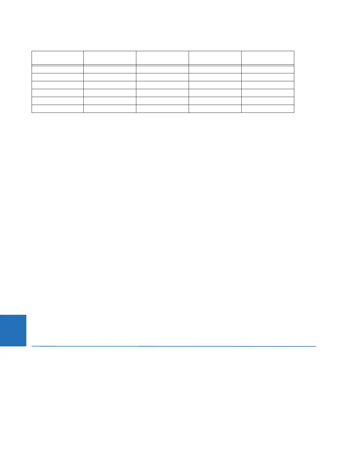
Table 8-3: Limits of linear operation of the CTS
The third and fourth columns of the table have the following significance.
If an external fault occurs on circuit C-1, then CT-1 carries the fault current. As the fault current is higher than any of the
other currents, the current supplied by CT-1 is used as the restraint signal. CT-1 is guaranteed to saturate if the current
exceeds 89.55 A secondary, or 17.9 times its rated current, or 8.96 pu of the bus differential zone. Consequently,
considering CT-1, the value of 8.96 pu is used as the higher breakpoint of the characteristic.
Considering CTs that can be connected (depending on the positions of the switches) to the North bus, the
HIGH BPNT for the
North bus zone is selected as the minimum of (8.96, 9.13, 31.17, 22.88, 24.57, 31.17), or 8.96 pu.
Considering CTs that can be connected (depending on the positions of the switches) to the South bus, the
HIGH BPNT for the
South bus zone is selected as the minimum of (9.13, 31.17, 22.88, 24.57, 31.17), or 9.13 pu.
8.3.3 Low breakpoint
The DC component in the primary current can saturate a given CT even with the AC current below the suggested value of
the higher breakpoint. The relay copes with this threat by using the Saturation Detector and applying a 2-out-of-2
operating principle upon detecting saturation.
The residual magnetism (remanence) left in the core of a CT can limit the linear operation of the CT significantly. It is
justified to assume that the residual flux can be as high as 80% of the saturation level leaving only 20% to accommodate
the flux component created by the primary current. This phenomenon can be reflected by reducing the saturation voltage
in the calculations by the factor of 100% / 20%, or 5. This, in turn, is equivalent to reducing the limit of linear operation by
the factor of 5, hence the last column in the Limits of Linear Operations of the CTs table.
For example, if the residual flux left in the core of the CT-1 is as high as 80% of its saturation level, the CT saturates at 17.92
A secondary, or 3.58 times its rated current, or at 1.79 pu of the bus differential zone.
The reduced limit of linear operation is used as the lower breakpoint of the biased differential characteristic (the
LOW BPNT
setting). In this way the interval spanning from the lower to higher breakpoints covers the indistinct area of possible
saturation due to the random factor of residual magnetism.
The
LOW BPNT is set at 1.79 pu for the North bus zone, and at 1.83 pu for the South bus zone.
A combination of very high residual magnetism and a DC component with a long time constant can saturate a given CT
even with the AC current below the suggested value of the lower breakpoint. The relay copes with this threat by using a 2-
out-of-2 operating mode for low differential currents.
8.4 Slopes and high set threshold
8.4.1 Description
To set the higher slope and threshold of the high set (unbiased) differential operation, external faults must be analyzed.
Consider an external fault for the North bus relay. It is justified to assume bus configurations that give maximum stress to
the maximum number of CTs. For this purpose we assume the tie breaker, B-7 closed; all the circuitry capable of supplying
the fault current to be in service; moreover, they are connected to the South bus in order to analyze the CT-7 and CT-8
carrying the fault current.
CT R
s
(Ω)I
max
(A sec) I
max
(pu)
(no remanence)
I
max
(pu)
(80% remanence)
CT-1 1.61 89.55 8.96 1.79
CT-2 1.58 91.25 9.13 1.83
CT-3 1.85 155.84 31.17 6.23
CT-4 1.75 137.30 22.88 4.58
CT-5, CT-6 1.63 147.42 24.57 4.91
CT-7, CT-8 1.85 155.84 31.17 6.23