CHAPTER 8: APPLICATION OF SETTINGS SLOPES AND HIGH SET THRESHOLD
B90 LOW IMPEDANCE BUS DIFFERENTIAL SYSTEM – INSTRUCTION MANUAL 8-9
8
8.4.3 External faults on C-2
The following table presents the results of analysis of an external fault on circuit C-2 (C-2 is connected to the North bus; C-
3, C-4 and C-5 are connected to the South bus).
By comparing the secondary currents (column 3 in the following table) with the limits of linear operation for the CTs
(column 4 shown earlier in the Limits of Linear Operations of the CTs table) it is concluded that CT-2 will saturate during this
fault producing a spurious differential signal. All other CTs do not saturate due to the AC components. The amount of the
spurious differential current (magnetizing current of CT-2) can be calculated using the burden, magnetizing characteristic,
and the primary current of the said CT.
For I
s
= 116.67 A, R
s
= 1.23 Ω and the characteristic shown earlier in the Approximate CT Magnetizing Characteristics
figure, the solution is I
magnetizing
= 27.69 A, I
relay
= 113.3 A.
The magnetizing current of the saturated CT-2 appears to the differential element protecting the North bus as a
differential signal of 27.69 A, while the restraint signal is the maximum of the bus currents (113.3 A). Consequently, the
higher slope of the characteristic should not be lower than 27.69 A / 113.3 A, or 24% and the pickup of the high-set
differential elements should not be lower than 27.69 A, or 2.77 pu.
Columns 6 and 7 of the following table summarize the DC saturation threat for the fault on C-2. CT-4, CT-6, CT-7, and CT-8
can saturate due to the DC components and can generate spurious differential signal for both the North and South bus
relays depending on the bus configuration. The saturation does not occur before 5.06 ms and is detected by the Saturation
Detector.
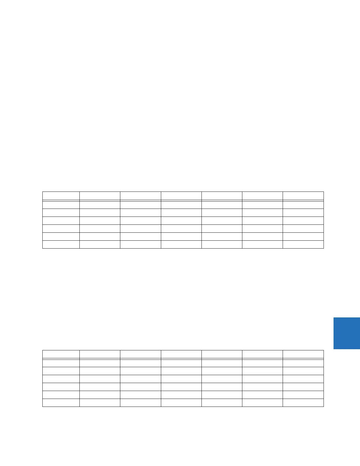
Table 8-5: External fault calculations on C-2
8.4.4 External faults on C-3
The following table presents the results of analysis of an external fault on circuit C-3 (C-3 is connected to the North bus; C-
4 and C-5 are connected to the South bus).
By comparing the secondary currents (column 3 in the table below) with the limits of linear operation for the CTs (column 4
in the Limits of Linear Operations of the CTs table shown earlier), it is concluded that none of the CTs saturate due to the AC
currents during this fault.
Columns 6 and 7 of the table below summarize the DC saturation threat for the fault on C-3. CT-3, CT-4, CT-6, CT-7, and CT-
8 can saturate due to the DC components and can generate a spurious differential signal for both the North and South bus
relays depending on the bus configuration. The saturation does not occur before 23.68 ms and is detected by the
Saturation Detector.
Table 8-6: Calculations for the external faults on C-3
CT I
FAULT
(kA) I
FAULT
(A sec) T
DC
(ms) AC saturation DC saturation t
SAT
(ms)
CT-1 0 0.00 N/A No No N/A
CT-2 14.0 116.67 40 Yes Yes 5.06
CT-3 6.0 25.00 5 No No N/A
CT-4 5.0 25.00 30 No Yes 26.37
CT-6 3.0 15.00 40 No Yes 61.50
CT-7, CT-8 14.0 58.33 40 No Yes 9.44
CT I
FAULT
(kA) I
FAULT
(A sec) T
DC
(ms) AC saturation DC saturation t
SAT
(ms)
CT-1 0 0.00 N/A No No N/A
CT-2 0 0.00 N/A No No N/A
CT-3 8.0 33.33 40 No Yes 23.68
CT-4 5.0 25.00 30 No Yes 26.37
CT-6 3.0 15.00 40 No Yes 61.50
CT-7, CT-8 8.0 33.33 40 No Yes 23.68