CHAPTER 3: INSTALLATION PANEL CUTOUTS
B90 LOW IMPEDANCE BUS DIFFERENTIAL SYSTEM – INSTRUCTION MANUAL 3-5
3
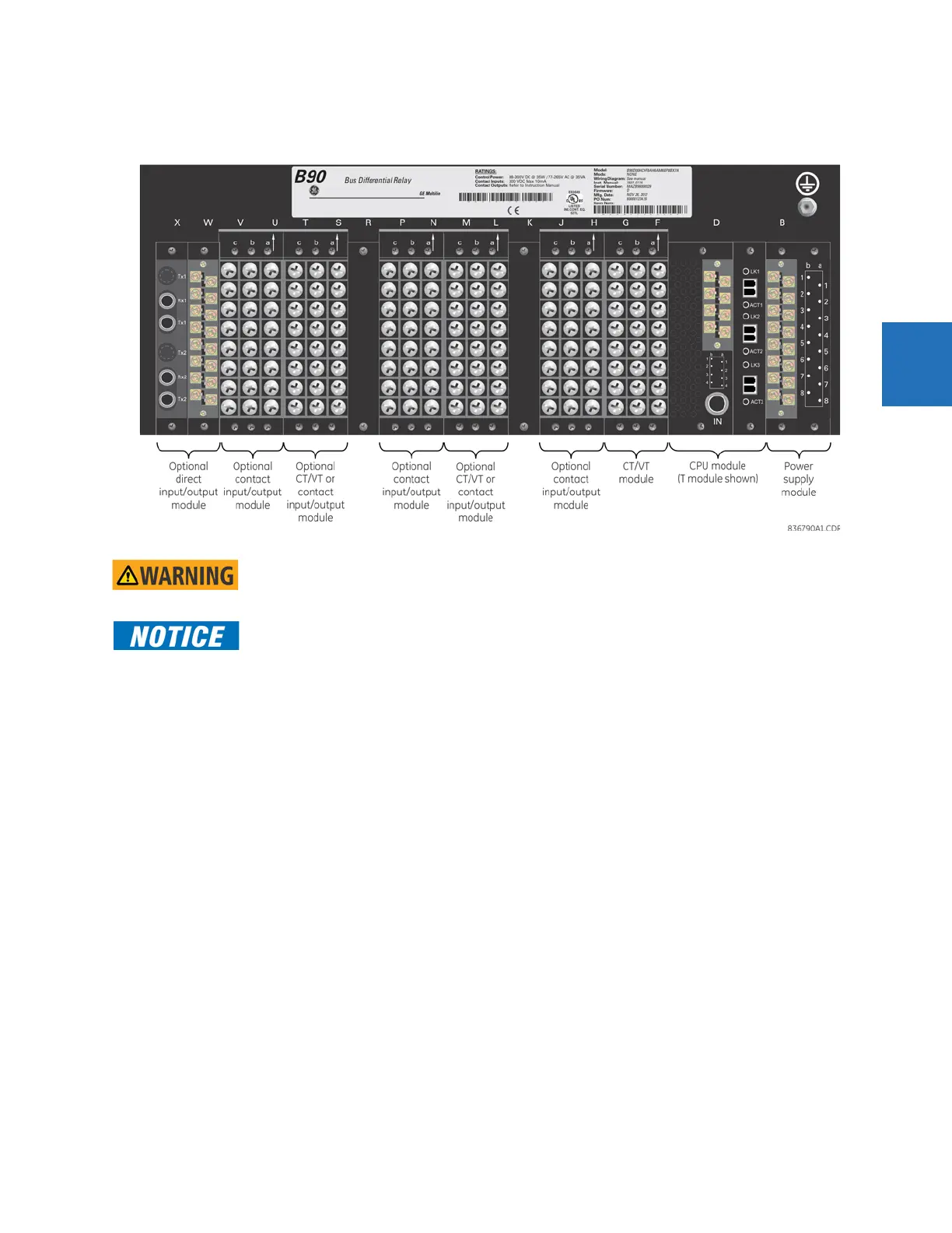
3.2.1 Rear terminal layout
The relay follows a convention with respect to terminal number assignments, which are three characters long and
assigned by module slot position, row number, and column letter. Two-slot wide modules take their slot designation from
the first slot position (nearest to CPU module), indicated by an arrow marker on the terminal block. The figure shows an
example of rear terminal assignments.
Do not touch any rear terminals while the relay is energized, else death or serious injury can
result from electrical shock.
The small form-factor pluggable ports (SFPs) are pluggable transceivers. They transmit and receive
and convert electrical signals to optical signals and vice-versa. They are inserted into the Ethernet
ports on the CPU module. A photo in the Maintenance chapter shows this plug-in device. Do not use
non-validated transceivers or install validated transceivers in the wrong Ethernet slot, else damage
can occur.