3-6 B90 LOW IMPEDANCE BUS DIFFERENTIAL SYSTEM – INSTRUCTION MANUAL
PANEL CUTOUTS CHAPTER 3: INSTALLATION
3
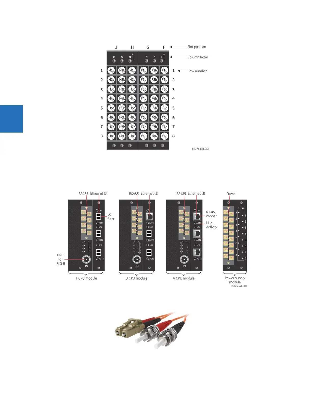
Figure 3-5: Example of modules in F and H slots
The torque used to connect the screws that connect the terminal blocks (screws a, b, c) and the metal plates over empty
slots to the chassis is 9 inch-pounds. For the screws used to wire the terminal blocks (rows 1 to 8), use 19
±1 inch-pounds.
During manufacturing, the power supply and CPU modules are installed in slots B and D of the chassis with 13 inch-pounds
of torque on the screws at the top and bottom of the modules. Wire connections to these two modules at 13 inch-pounds.
Figure 3-6: CPU modules and power supply
The following figure shows the optical connectors for CPU modules.
Figure 3-7: LC fiber connector (left) and ST fiber connector (right)