CHAPTER 5: SETTINGS GROUPED ELEMENTS
B90 LOW IMPEDANCE BUS DIFFERENTIAL SYSTEM – INSTRUCTION MANUAL 5-169
5
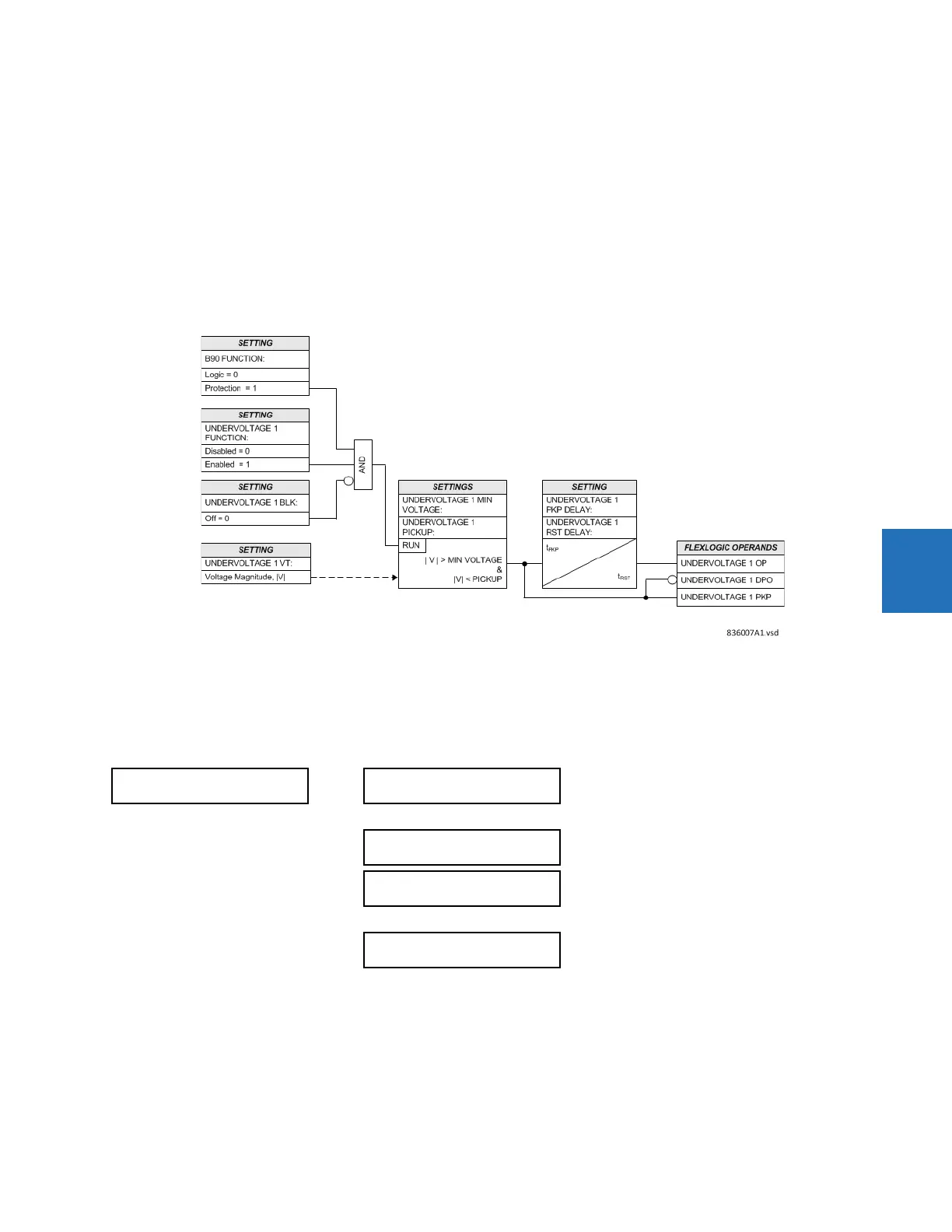
Application of the Undervoltage element is beneficial during CT trouble conditions. A low-voltage check prevents
maloperation of the main protection until the CT trouble element (differential current alarm) operates. The CT Trouble
element is user-configurable to block selected protection functions indefinitely. Voltage supervision alone does not
guarantee security because a CT trouble may be followed by an external fault causing a low-voltage condition.
Voltage pickup is set in per-unit values. The nominal voltage as entered in the
SYSTEM SETUP AC INPUTS VOLTAGE BANK
## VT ## SECONDARY
setting corresponds to 1 pu. The minimum voltage setting (UNDERVOLTAGE 1 MIN VOLTAGE)
specifies the minimum voltage required for element operation. This setting discriminates between undervoltage conditions
for energized and de-energized circuits. If the element is used for low-voltage supervision, set this value to 0.004.
The Undervoltage element is enabled only when
PRODUCT SETUP B90 FUNCTION B90 FUNCTION is set to “Protection”.
One element is available per each voltage input of the relay.
Figure 5-90: Undervoltage logic
5.6.6 Current elements
5.6.6.1 Menu
SETTINGS GROUPED ELEMENTS SETTING GROUP 1(6) CURRENT ELEMENTS
5.6.6.2 Inverse TOC curve characteristics
The inverse time overcurrent curves used by the time overcurrent elements are the IEEE, IEC, GE Type IAC, and I
2
t standard
curve shapes. This allows for simplified coordination with downstream devices.
CURRENT ELEMENTS
INSTANTANEOUS
OVERCURRENT 1
See page 5-174
INSTANTANEOUS
OVERCURRENT 24
TIME
OVERCURRENT 1
See page 5-175
TIME
OVERCURRENT 24