CHAPTER 3: INSTALLATION DIRECT INPUT AND OUTPUT COMMUNICATIONS
B90 LOW IMPEDANCE BUS DIFFERENTIAL SYSTEM – INSTRUCTION MANUAL 3-33
3
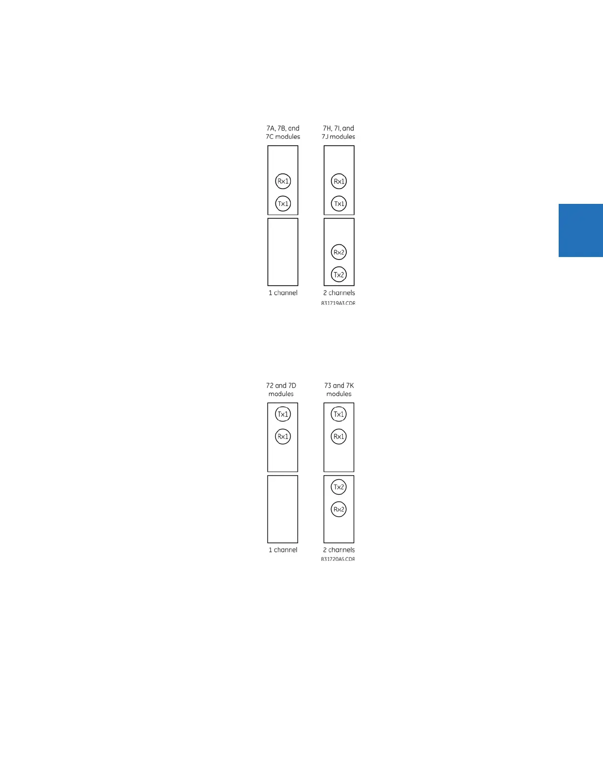
3.4.2 Fiber: LED and ELED transmitters
The following figure shows the configuration for the 7A, 7B, 7C, 7H, 7I, and 7J fiber-only modules.
Figure 3-32: LED and ELED fiber modules
3.4.3 Fiber laser transmitters
The following figure shows the configuration for the 72, 73, 7D, and 7K fiber-laser modules.
Figure 3-33: 7x Laser fiber modules
The following figure shows configuration for the 2I and 2J fiber-laser modules.