4-40 B90 LOW IMPEDANCE BUS DIFFERENTIAL SYSTEM – INSTRUCTION MANUAL
FRONT PANEL INTERFACE CHAPTER 4: INTERFACES
4
All elements that are able to discriminate faulted phases can independently turn off or on the phase A, B, or C LEDs. This
includes phase instantaneous overcurrent, phase undervoltage, and so on. This means that the phase A, B, and C operate
operands for individual protection elements are ORed to turn on or off the phase A, B, or C LEDs.
• VOLTAGE — Indicates voltage was involved
• CURRENT — Indicates current was involved
• FREQUENCY — Not used
• <blank> — Always off by default
• ZONE 1 — Indicates bus differential zone 1 was involved
• ZONE 2 — Indicates bus differential zone 2 was involved
• ZONE 3 — Indicates bus differential zone 3 was involved
• ZONE 4 — Indicates bus differential zone 4 was involved
• OTHER — Indicates a composite function was involved, BUS 5 OP was asserted, or BUS 6 OP was asserted. For the
B90, a composite function means either any Digital Element OP or any TRIP BUS OP.
The user-programmable LEDs consist of 48 amber LED indicators in four columns. The operation of these LEDs is user-
defined. Support for applying a customized label beside every LED is provided. Default labels are shipped in the label
package of every B90, together with custom templates. The default labels can be replaced by user-printed labels.
User customization of LED operation is of maximum benefit in installations where languages other than English are used
to communicate with operators. See the User-Programmable LEDs section in chapter 5 for the settings used to program
the operation of the LEDs on these panels.
4.2.4.2 Standard front panel
The standard front panel consists of three panels with LED indicators, keys, and a communications port. The RESET key is
used to reset any latched LED indicator or target message, once the condition has been cleared (these latched conditions
can also be reset via the
SETTINGS INPUT/OUTPUTS RESETTING menu). The RS232 port is for connection to a
computer.
The
USER keys are not used in this unit.
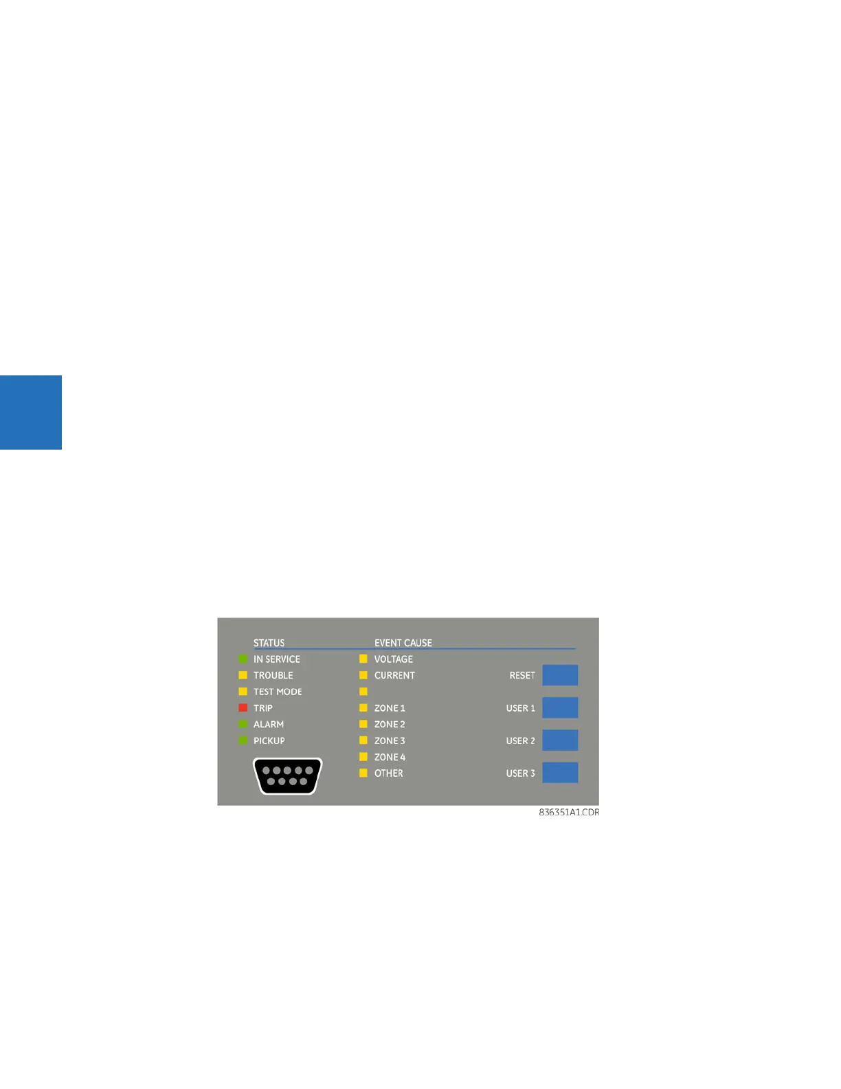
Figure 4-47: LED panel 1
Status indicators
• IN SERVICE — Indicates that control power is applied, all monitored inputs/outputs and internal systems are fine, and
the relay is in (online) Programmed mode (under Settings > Product Setup > Installation)
• TROUBLE — Indicates that the relay has detected an internal problem. Check the self-test messages outlined at the
end of the Commands and Targets chapter, and view the event records under Actual Values > Records. For a beta /
pre-release, this LED is always on.
• TEST MODE — Indicates that the relay is in test mode. For information, see the Test Mode section in the Settings
chapter.