4-62 B90 LOW IMPEDANCE BUS DIFFERENTIAL SYSTEM – INSTRUCTION MANUAL
FLEXLOGIC DESIGN USING ENGINEER CHAPTER 4: INTERFACES
4
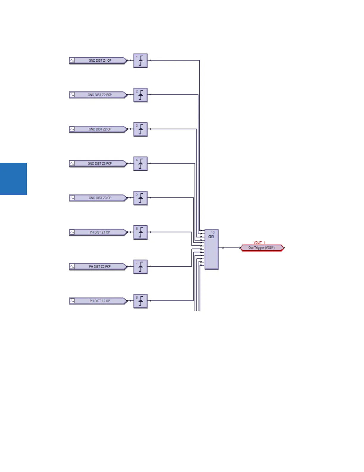
Figure 4-64: Inputs triggering output in Engineer
The process is as follows:
• Modify or create a logic diagram in the Offline Window area of the EnerVista UR Setup software
• Compile it and troubleshoot any errors
• The logic populates automatically into the FlexLogic Equation Editor
• Upload the file to the live device
• Monitor the output
This section explains how to use Engineer. It outlines the following topics:
• Design logic
• Send file to and from device
• Monitor logic
•View front panel
• Generate connectivity report
•Preferences