CHAPTER 4: INTERFACES FLEXLOGIC DESIGN USING ENGINEER
B90 LOW IMPEDANCE BUS DIFFERENTIAL SYSTEM – INSTRUCTION MANUAL 4-65
4
the device in the Online Window area and select the Add Device to Offline Window option.
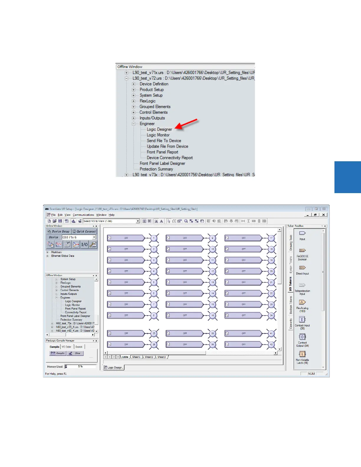
Figure 4-68: Access Engineer in the Offline Window area
The default block diagram opens, which shows 48 inputs (boxes) and 48 user-programmable LEDs (circles).
Figure 4-69: Default view of FlexLogic designer
2. Optionally delete the default logic diagram by right-clicking its tab at the bottom of the window and selecting Delete.
3. To add a blank sheet, click Edit > Add Sheet. A new tab displays. Or use the last tab displayed, which is a blank sheet.
4. Optionally right-click the new tab and Rename it.
5. Add the input blocks to the logic diagram. For example, click the I/O Tokens tab on the right, click the Input element,
then click in the logic sheet to add it. Or drag-and-drop it.