CHAPTER 5: SETTINGS PRODUCT SETUP
B90 LOW IMPEDANCE BUS DIFFERENTIAL SYSTEM – INSTRUCTION MANUAL 5-115
5
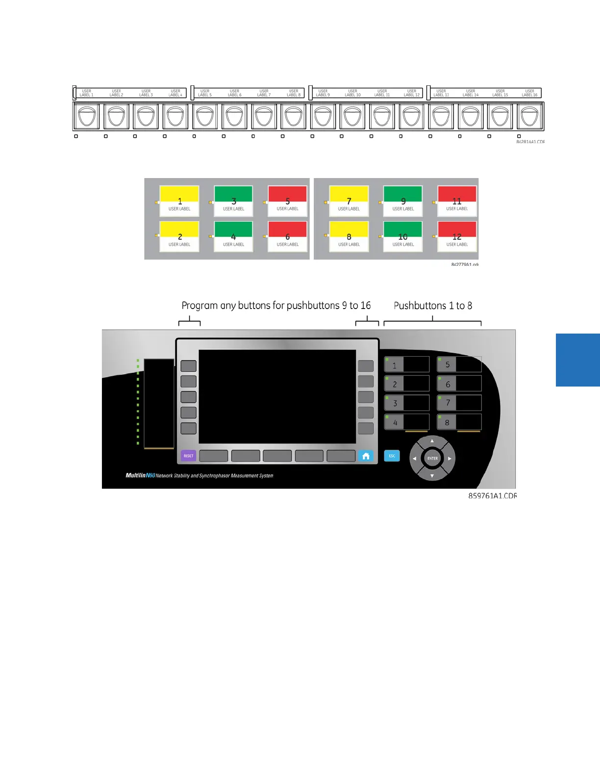
Figure 5-51: User-programmable pushbuttons (enhanced front panel)
Figure 5-52: User-programmable pushbuttons (standard front panel)
Figure 5-53: User-programmable pushbuttons (graphical front panel)
Front panel pushbuttons and LEDs can be custom labelled as outlined in the Front Panel Labelling section in the previous
chapter.
Each pushbutton asserts its own “On” and “Off” FlexLogic operands (for example, PUSHBUTTON 1 ON and PUSHBUTTON 1 OFF).
These operands are available for each pushbutton and are used to program specific actions. If any pushbutton is active,
the ANY PB ON operand is asserted.
Each pushbutton has an associated LED indicator. By default, this indicator displays the present status of the
corresponding pushbutton (on or off). However, each LED indicator can be assigned to any FlexLogic operand through the
PUSHBTN 1 LED CTL setting.
The activation and deactivation of user-programmable pushbuttons depends on whether latched or self-reset mode is
programmed.
• Latched mode — In latched mode, a pushbutton can be set (activated) by asserting the operand assigned to the
PUSHBTN 1 SET setting, by directly pressing the associated front panel pushbutton, or with the graphical front panel
interface. The state of each pushbutton is stored in non-volatile memory and maintained through a loss of control
power.