5-180 B90 LOW IMPEDANCE BUS DIFFERENTIAL SYSTEM – INSTRUCTION MANUAL
CONTROL ELEMENTS CHAPTER 5: SETTINGS
5
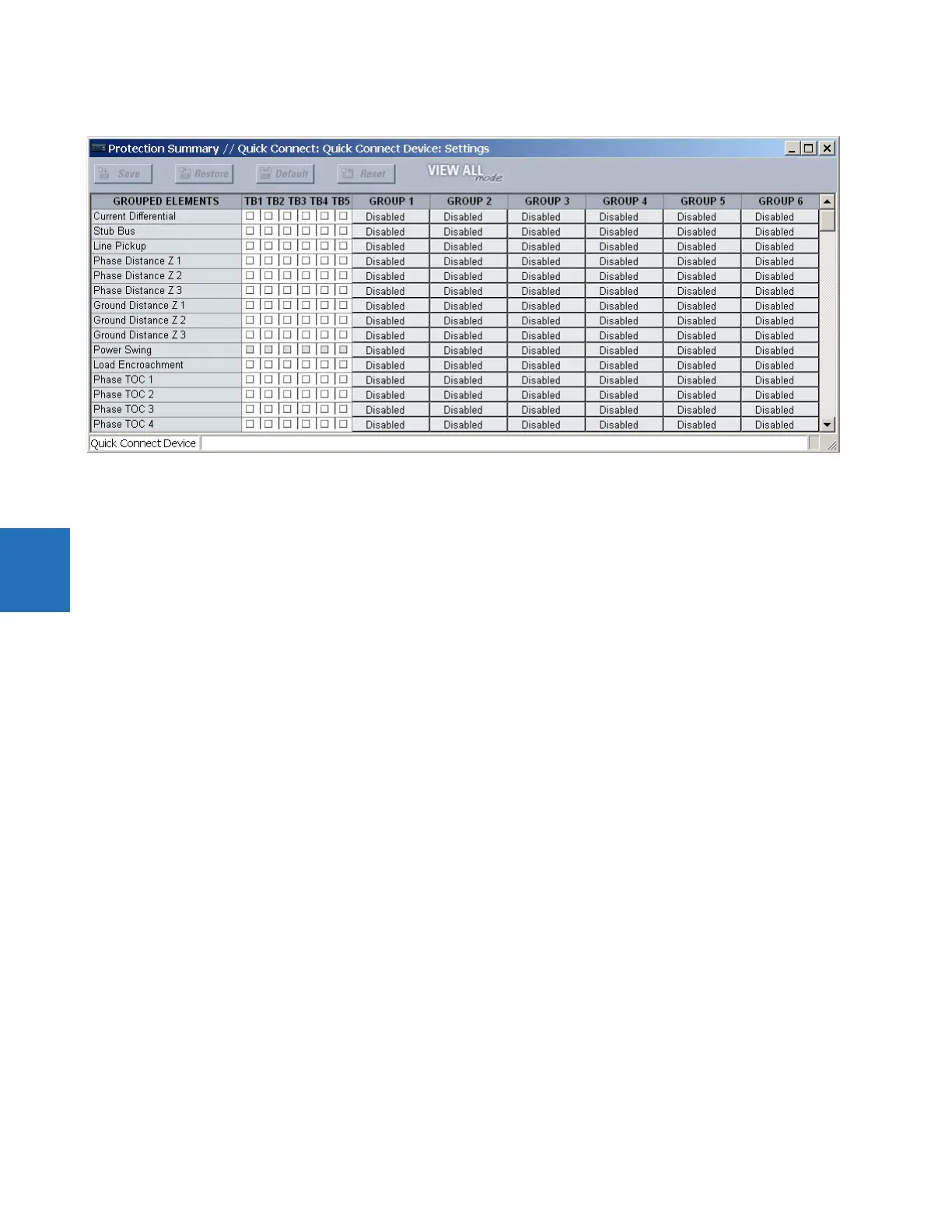
Figure 5-96: Trip bus fields in the protection summary
The following settings are available.
TRIP BUS 1 BLOCK — The trip bus output is blocked when the operand assigned to this setting is asserted.
TRIP BUS 1 PICKUP DELAY — This setting specifies a time delay to produce an output depending on how output is used.
TRIP BUS 1 RESET DELAY — This setting specifies a time delay to reset an output command. Set the time delay long enough
to allow the breaker or contactor to perform a required action.
TRIP BUS 1 INPUT 1 to TRIP BUS 1 INPUT 16 — These settings select a FlexLogic operand to be assigned as an input to the trip
bus.
TRIP BUS 1 LATCHING — This setting enables or disables latching of the trip bus output. This is typically used when lockout is
required or user acknowledgement of the relay response is required.
TRIP BUS 1 RESET — The trip bus output is reset when the operand assigned to this setting is asserted. Note that the RESET OP
operand is pre-wired to the reset gate of the latch, As such, a reset command from the front panel interface or via
communications resets the trip bus output.