5-186 B90 LOW IMPEDANCE BUS DIFFERENTIAL SYSTEM – INSTRUCTION MANUAL
CONTROL ELEMENTS CHAPTER 5: SETTINGS
5
5.7.5.2 CT trouble zone (ANSI 50/74)
SETTINGS CONTROL ELEMENTS MONITORING ELEMENTS CT TROUBLE ZONE 1(6)
The CT Trouble feature is available only when
PRODUCT SETUP B90 FUNCTION B90 FUNCTION is set to "Protection".
This element uses the differential current calculated in accordance with the bus configuration programmed under Bus
Zone 1. Operation of this element is therefore completely dependent on the dynamic bus replica, which must be defined
first. The bus differential zones are defined using the path
SETTINGS SYSTEM SETUP BUS. The CT Trouble element 1
detects CT problems in any of the circuits actually connected to the differential zone defined as Bus Zone 1.
The
CT TROUBLE ZONE 1 PICKUP setting specifies the differential current level that defines an abnormal bus state. If the
differential current in a given phase remains above this level for the time interval defined by the
CT TROUBLE ZONE 1 DELAY
setting, CT Trouble is declared for the given phase by setting the appropriate FlexLogic output operand. The operand may
be configured to raise an alarm and block the bus differential function for the corresponding zone of protection.
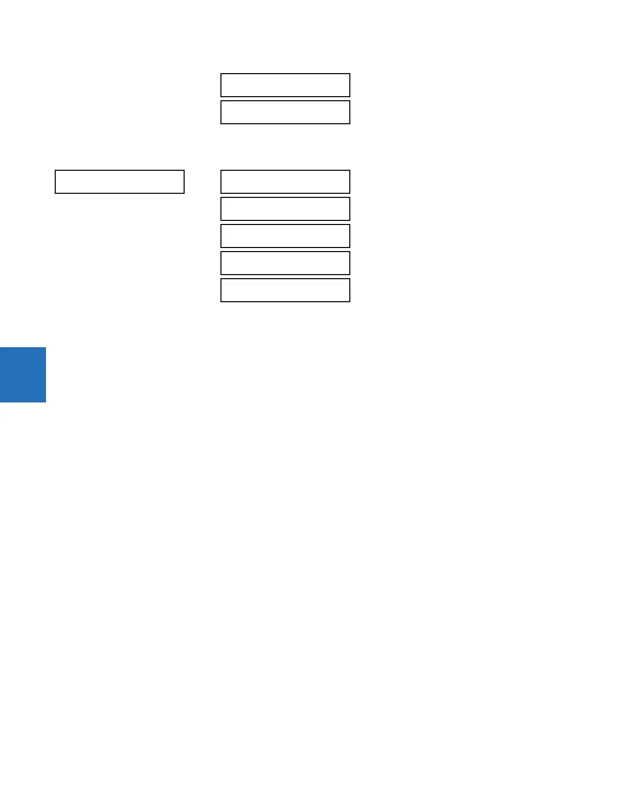
CT TROUBLE ZONE 6
BUS REPLICA
See page 5-187
CT TROUBLE ZONE 1
CT TROUBLE ZONE 1
FUNCTION: Disabled
Range: Disabled, Enabled
CT TROUBLE ZONE 1
PICKUP: 0.100 pu
Range: 0.020 to 2.000 pu in steps of 0.001
CT TROUBLE ZONE 1
DELAY: 1.0 s
Range: 1.0 to 60.0 s in steps of 0.1
CT TROUBLE ZONE 1
TARGET: Self-reset
Range: Self-reset, Latched, Disabled
CT TROUBLE ZONE 1
EVENTS: Disabled
Range: Disabled, Enabled