CHAPTER 3: INSTALLATION WIRING
B90 LOW IMPEDANCE BUS DIFFERENTIAL SYSTEM – INSTRUCTION MANUAL 3-21
3
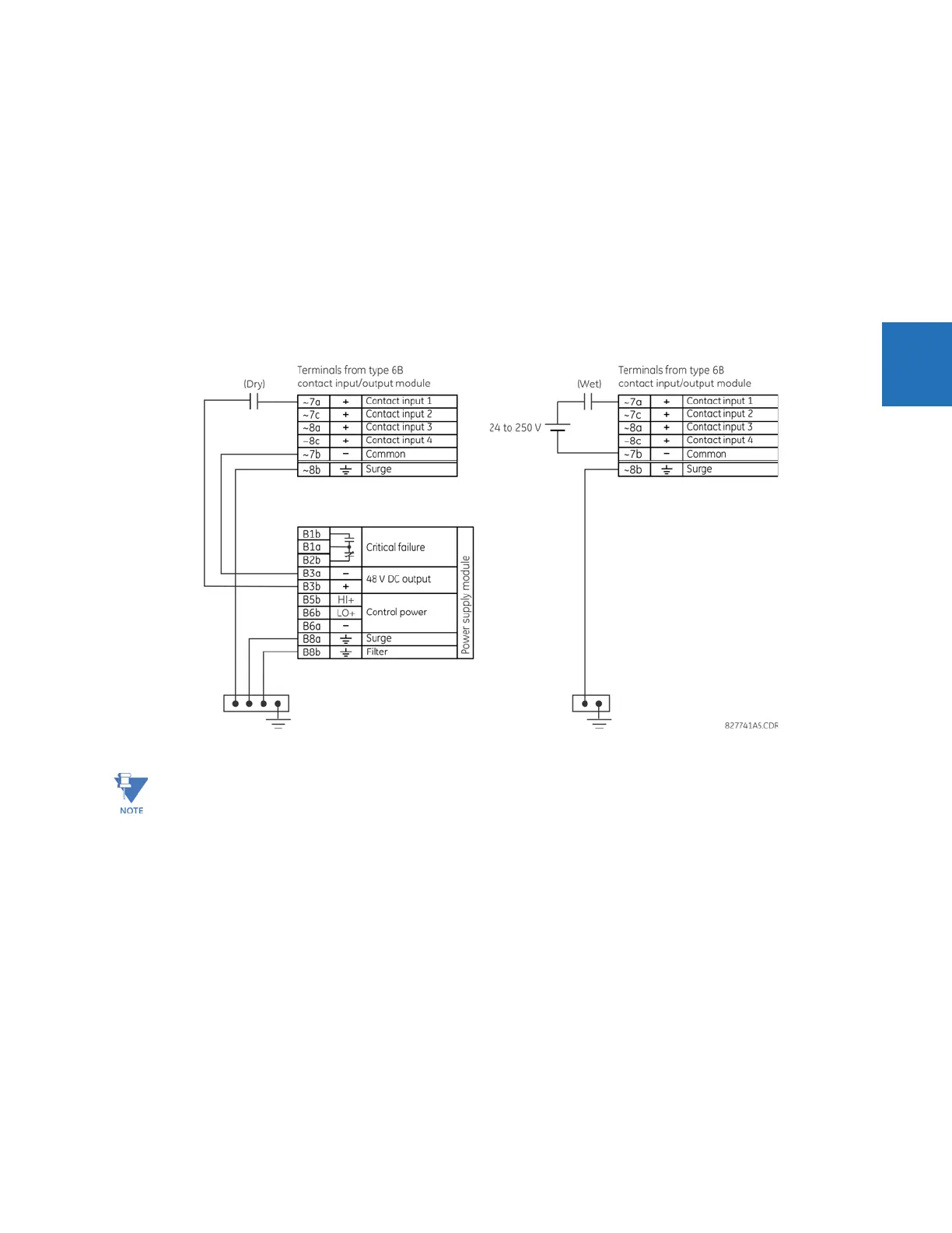
3.3.5.1 Contact inputs
A dry contact has one side connected to terminal B3b. This is the positive 48 V DC voltage rail supplied by the power supply
module. The other side of the dry contact is connected to the required contact input terminal. Each contact input group
has its own common (negative) terminal that must be connected to the DC negative terminal (B3a) of the power supply
module. When a dry contact closes, a current of 1 to 3 mA flows through the associated circuit.
A wet contact has one side connected to the positive terminal of an external DC power supply. The other side of this
contact is connected to the required contact input terminal. If a wet contact is used, then the negative side of the external
source must be connected to the relay common (negative) terminal of each contact group. The maximum external source
voltage for this arrangement is 300 V DC.
The voltage threshold at which each group of four contact inputs detects a closed contact input is programmable as
17 V DC for 24 V sources, 33 V DC for 48 V sources, 84 V DC for 110 to 125 V sources, and 166 V DC for 250 V sources.
Figure 3-18: Dry and wet contact input connections
There is no provision in the relay to detect a DC ground fault on 48 V DC control power external output. We recommend
using an external DC supply.
3.3.5.2 General application considerations
Contacts outputs of protective relays, auxiliary contacts from breakers, disconnectors and other devices, are generally
connected to contacts inputs of protective relays. In some situations, the contact outputs of some protective relays can
have high impedance connected across it. When such a contact output is connected across a B90 contact input, it can
spuriously operate the B90 input even when the output is open, if there is a substantial distributed capacitance
(represented by C1) present in the wiring between the output and the B90 input and the debounce time setting in the B90
relay is low enough. This false assertion of the contact input, when there is inadvertent ground present at the DC positive
terminal, can be prevented by inserting a resistor across the B90 input.
The following figure shows a typical DC circuit, with battery ground detection, of contact input. The contact output has
parallel impedance across it (represented by R1).
Where a tilde “~” symbol appears, substitute the slot position of the module.