2–2 D485 MODBUS TO DEVICENET CONVERTER – USER GUIDE
INSTALLATION
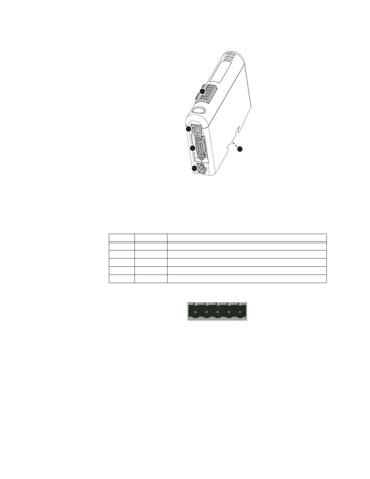
Figure 2-1: D485 electrical connections
DEVICENET CONNECTOR The DeviceNet connector is indicated as A in the figure above. This connector is used to
connect the D485 to the
DeviceNet network.
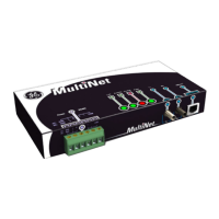
The pin assignments for the
DeviceNet connector are shown below.
Figure 2-2: DeviceNet connector
Table 2–1: DeviceNet connector pin assignments
Pin Signal Description
1 V– DeviceNet bus power, negative supply voltage
2 CAN L CAN L bus line
3 Shield Cable shield
4 CAN H CAN H bus line
5 V+ DeviceNet bus power, positive supply voltage