7–2 D485 MODBUS TO DEVICENET CONVERTER – USER GUIDE
MODBUS NETWORK AND NODE MONITORS
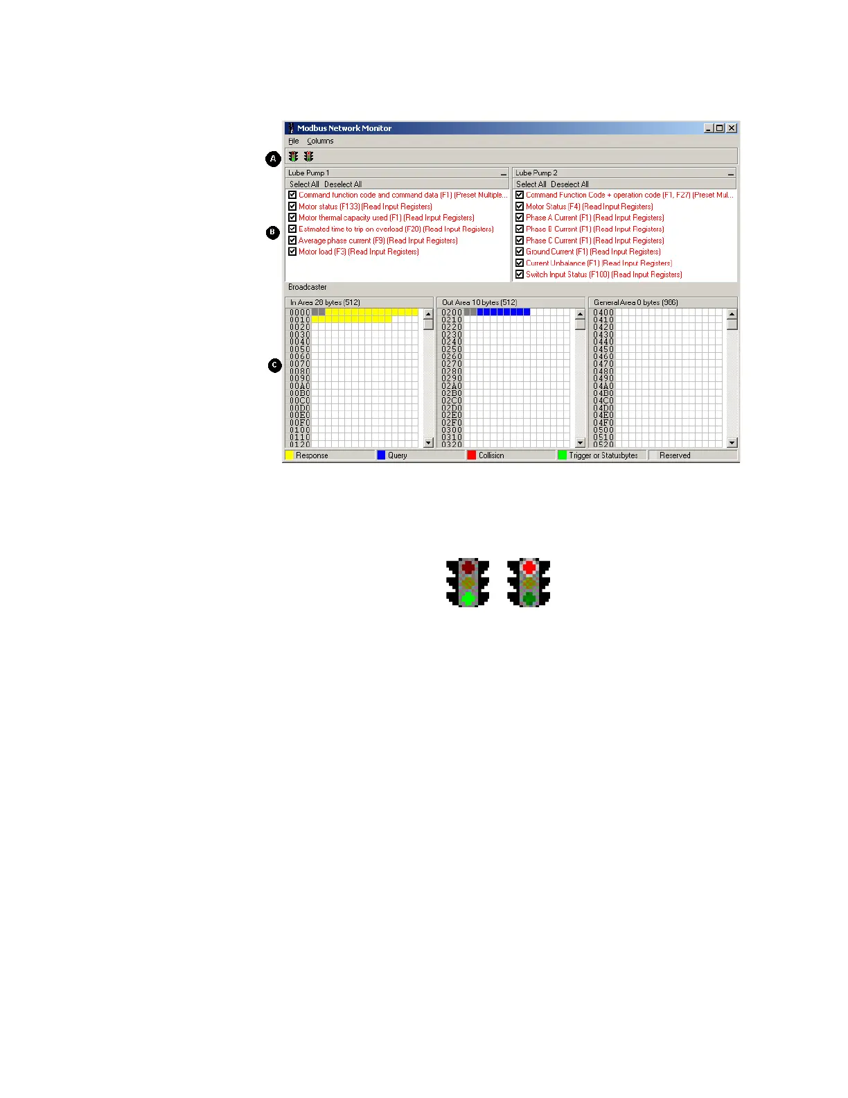
OPERATION The Modbus network monitor window is shown below.
Figure 7-1: Modbus network monitor
A: Start/stop sub-network scanning
These icons are used to start / stop the scanning of the Modbus network. To stop the
scanning, click on the red light. To start scanning again, simply click on the green light.
B: Nodes/transactions
To view data blocks linked to a single command, select the command and the data will
appear in the monitor area, see below. (C)
C: Monitor Area: input / output / general data areas
These areas display the data allocated in the input, output and general data areas. This
information is color coded as follows:
• White: No data allocated.
• Yellow: Data allocated by a response/consume transaction.
• Blue: Data allocated by a query/produce transaction.
• Red: Collision. This area has been allocated more than once.
• Grey: Data allocated by the control/status registers.