2–6 D485 MODBUS TO DEVICENET CONVERTER – USER GUIDE
INSTALLATION
CONFIGURATION
SWITCHES
The configuration switches are used to set the DeviceNet MAC ID and baud rate settings.
Normally, these switches are covered by a plastic hatch. Note that the node address can
not be changed during runtime, i.e. the D485 requires a reset for any changes to have
effect. Recycle the power supply to reset the module.
Figure 2-10: D485 configuration switches
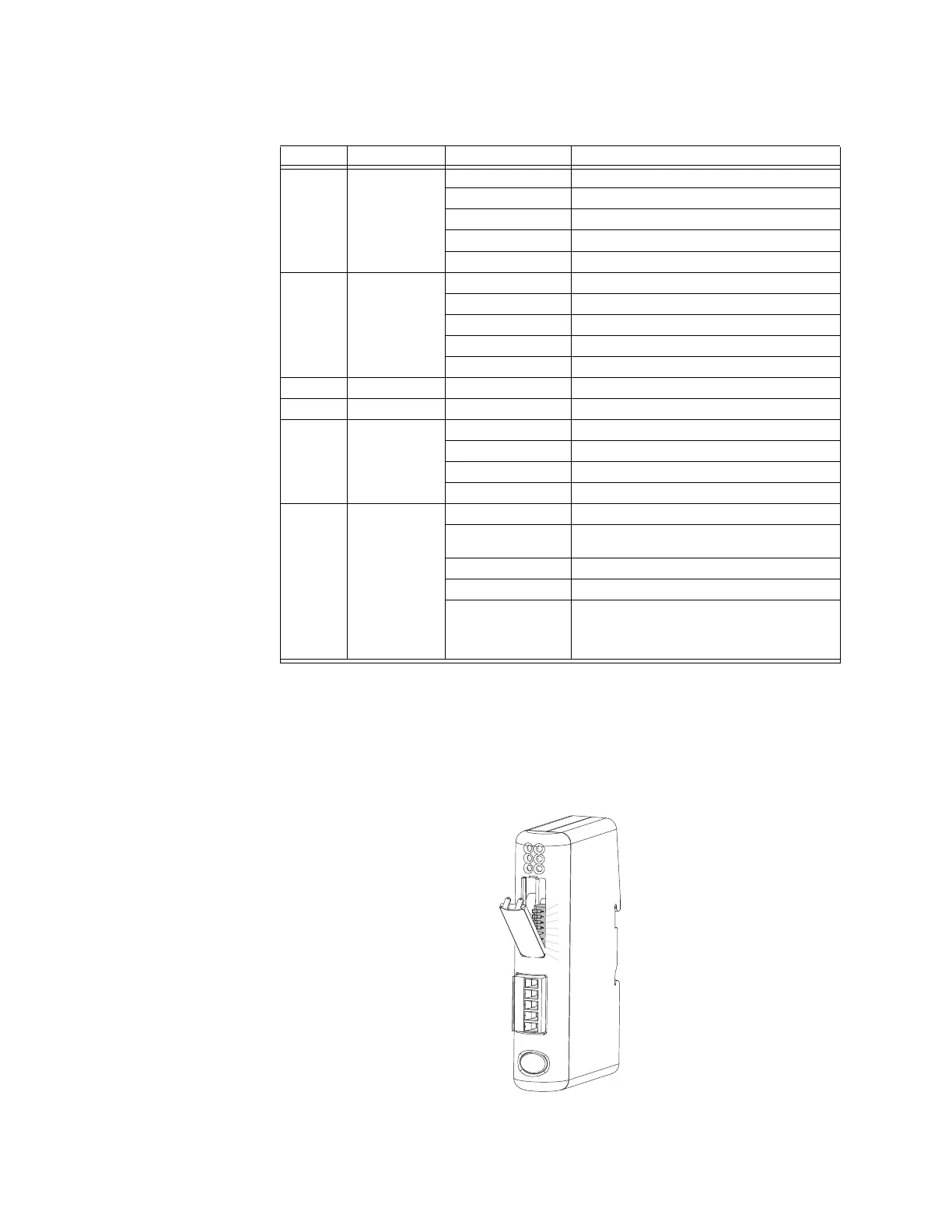
Table 2–5: D485 status indicators
Number Description State Status
1 Network status Off Not powered / not online
Green Link OK, online, connected
Green flashing Online, not connected
Red Critical link failure
Red flashing Connection timeout
2 Module status Off No power to device
Green Device operational
Green flashing Data size larger than configured
Red Unrecoverable fault
Red flashing Minor fault
3Not used- -
4Not used- -
5 Modbus
status *
Off Power off
Green, flashing Initializing and not running
Green Running
Red Stopped or subnet error, or timeout
6 Device status Off Power off
Red/green
alternating
Invalid or missing configuration
Green Initializing
Green flashing Running
Red flashing If the device status LED is flashing in a
sequence starting with one or more red
flashes, note the sequence pattern and
contact GE Multilin
* This LED turns green when all transactions have been active at least once. This includes any
transactions using “change of state” or “change of state on trigger”. If a timeout occurs on a
transaction, this LED will turn red.